
TM 5-2420-231-23-3
0286
DISASSEMBLY CONTINUED
NOTE
Note adjustment of stop bolt to aid in assembly.
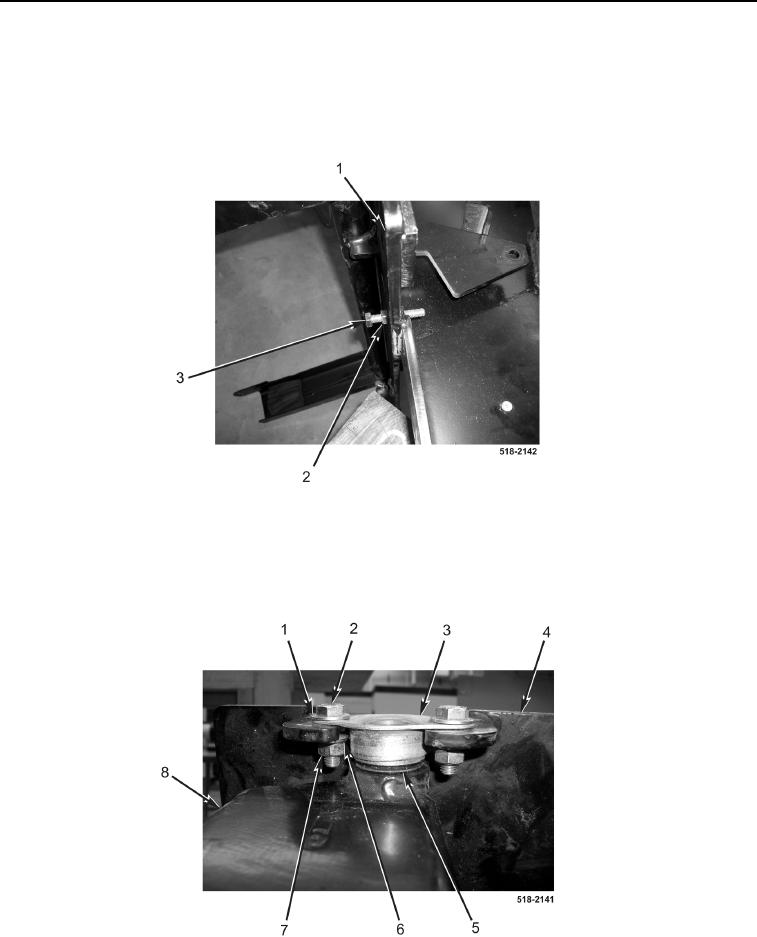
14. Loosen jamnut (Figure 15, Item 2) and remove stop bolt (Figure 15, Item 3) from backhoe control tower
(Figure 15, Item 1).
Figure 15. Stop Bolt.
0286
15. With assistance, remove four nuts (Figure 16, Item 7), lockwashers (Figure 16, Item 6), eight washers
(Figure 16, Item 1), four bolts (Figure 16, Item 2), two bushings (Figure 16, Item 3), and washers (Figure 16,
Item 5) from backhoe control tower (Figure 16, Item 8). Discard lockwashers.
16. With assistance, separate backhoe control tower (Figure 16, Item 8) from backhoe control tower mounting
bracket (Figure 16, Item 4).
Figure 16. Backhoe Control Tower Bushings.
0286
END OF TASK