
TM 5-2420-231-23-3
0289
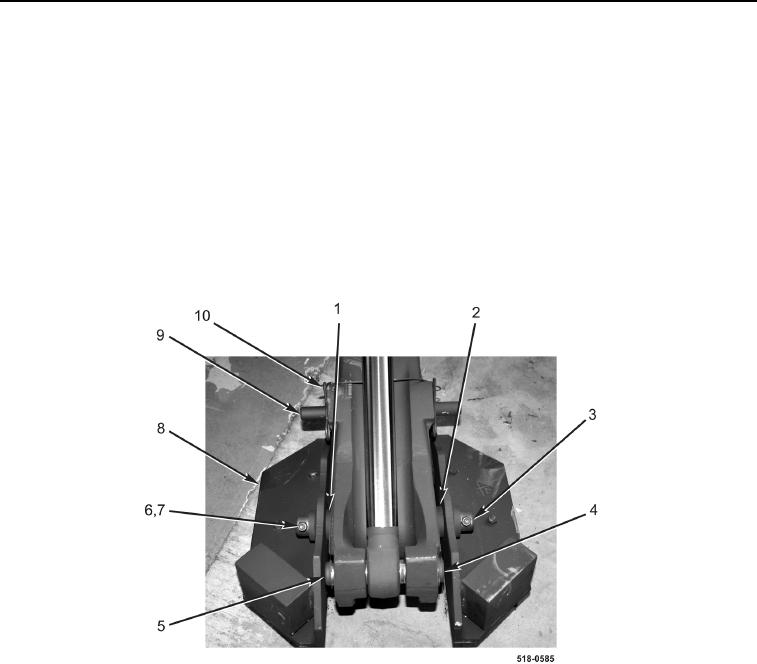
INSTALLATION CONTINUED
4. With assistance, install stabilizer pad assembly (Figure 4, Item 8) on machine.
5. Lightly grease and install pin (Figure 4, Item 9) and two lockpins (Figure 4, Item 10) on stabilizer pad assembly
(Figure 4, Item 8).
NOTE
Install washers as noted during removal.
6. Lightly grease pin (Figure 4, Item 3).
7. Install washer (Figure 4, Item 1), two washers (Figure 4, Item 2), pin (Figure 4, Item 3), two bolts (Figure 4,
Item 6), and new locknuts (Figure 4, Item 7) on stabilizer pad assembly (Figure 4, Item 8).
8. Lightly grease and install pin (Figure 4, Item 4) and two retaining rings (Figure 4, Item 5) on machine.
Figure 4. Pad Assembly.
0289
END OF TASK
END OF WORK PACKAGE
0289-5/(6 blank)