
4
TM 5-2420-231-23-3
FIELD MAINTENANCE
-
BACKHOE STABILIZER ARM REPLACEMENT
0290
Removal, Cleaning and Inspection, Installation
INITIAL SETUP
Tools and Special Tools
Personnel Required
Tool Kit, General Mechanic's
Two
0
0
(WP 0376, Item 117)
References
Pliers, Retaining Ring, Fixed Tip, Convertible,
0
90/.090" Tips, 8-3/4" (WP 0376, Item 61)
0
WP 0374 (Group Number 0812)
Sledge, Double Face Hammer, 8-lb
0
0
(WP 0376, Item 78)
Equipment Conditions
Sling, Eye (Nylon, 4 ft x 1 in.)
Stabilizer plate and pad removed (WP 0289)
0
0
(WP 0376, Item 79)
Rear wheel and tire assembly removed
0
Lifting Device (500-lb capacity)
(WP 0217)
0
Materials/Parts
Estimated Time to Complete
Grease, Automotive and Artillery (GAA)
4.0 hr
0
0
(WP 0375, Item 14)
Rag, Wiping (WP 0375, Item 25)
0
REMOVAL
0290
NOTE
The procedure for stabilizer arm removal and replacement is identical for left-hand and
right-hand stabilizer arm. Left-hand stabilizer arm is shown in this procedure.
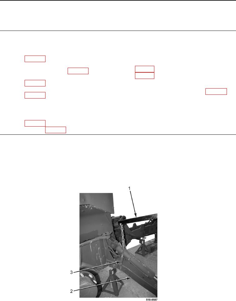
1. Install sling (Figure 1, Item 3) and lifting device (Figure 1, Item 1) on stabilizer arm (Figure 1, Item 2) and sup-
port stabilizer arm.
Figure 1. Support Stabilizer Arm.
0290