
TM 5-2420-231-23-3
0290
INSTALLATION
0290
WARNING
Use extreme caution when handling heavy parts. Provide adequate support and use
assistance during procedure. Ensure any lifting device used is in good condition and of
suitable load capacity. Keep clear of heavy parts supported only by lifting device. Failure
to follow this warning may result in injury or death to personnel.
NOTE
Stabilizer arm assembly weighs 173 lb (78 kg).
Install washers (shims) as noted during removal.
1. Lightly grease pin (Figure 2, Item 3).
2. With assistance, install stabilizer arm (Figure 2, Item 4), two washers (Figure 2, Item 1), pin (Figure 2, Item 3),
washer (Figure 2, Item 6), and two retaining rings (Figure 2, Items 2 and 5) on machine.
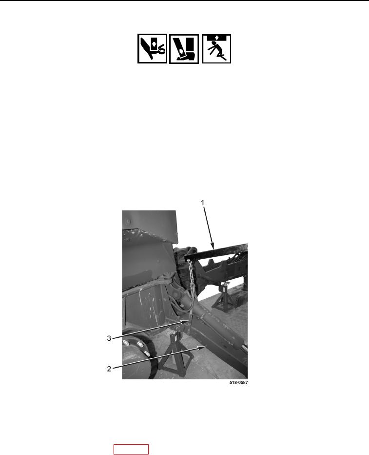
3. Remove sling (Figure 3, Item 3) and lifting device (Figure 3, Item 1) from stabilizer arm (Figure 3, Item 2).
Figure 3. Support Stabilizer Arm.
0290
END OF TASK
FOLLOW-ON TASKS
0290
1. Install rear wheel and tire assembly (WP 0217).
2. Install stabilizer plate and pad (WP 0289).
END OF TASK
END OF WORK PACKAGE
0290-3/(4 blank)