
TM 5-2420-231-23-3
0297
REMOVAL CONTINUED
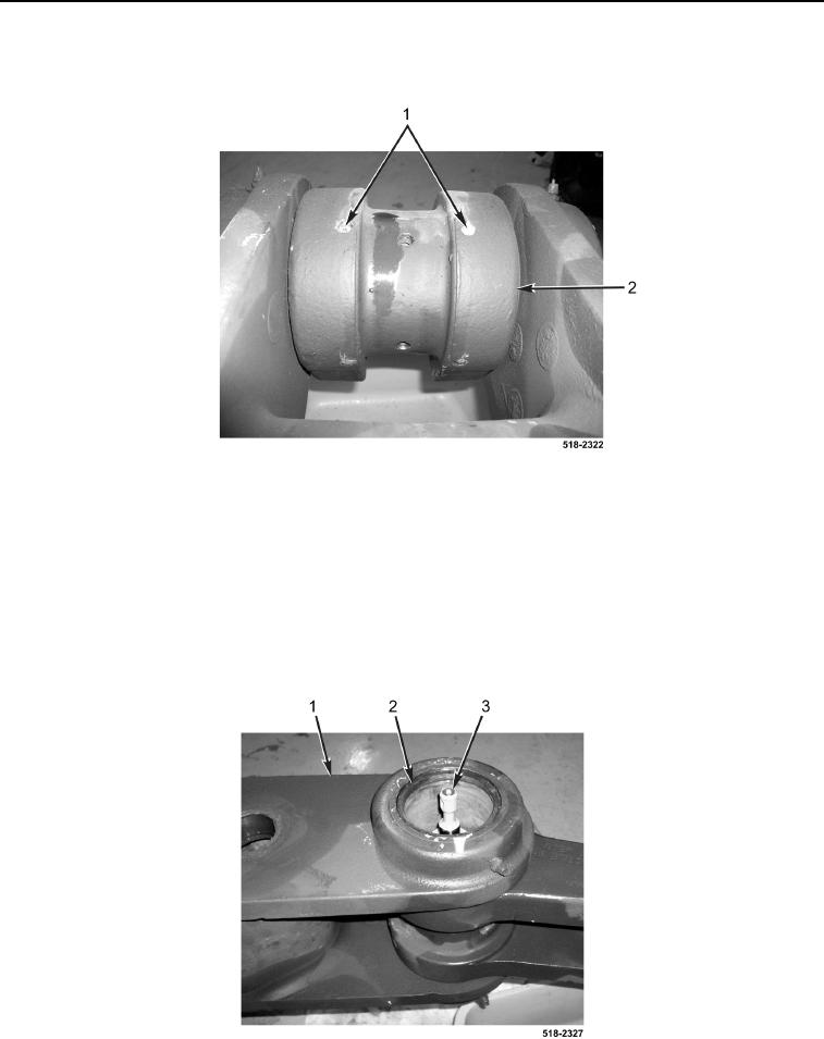
21. Remove four set screws (Figure 9, Item 1) from cylinder (Figure 9, Item 2).
Figure 9. Set Screws.
0297
22. Push coupler cylinder (Figure 10, Item 3) inward.
NOTE
Note location of coupler cylinder bushings and fittings to aid in installation.
23. Using backhoe coupler piston tool, remove coupler bushing (Figure 10, Item 2) and coupler cylinder
(Figure 10, Item 3) from backhoe dipper support arm (Figure 10, Item 1).
Figure 10. Coupler Bushing and Cylinder.
0297