
TM 5-2420-231-23-3
0297
INSTALLATION CONTINUED
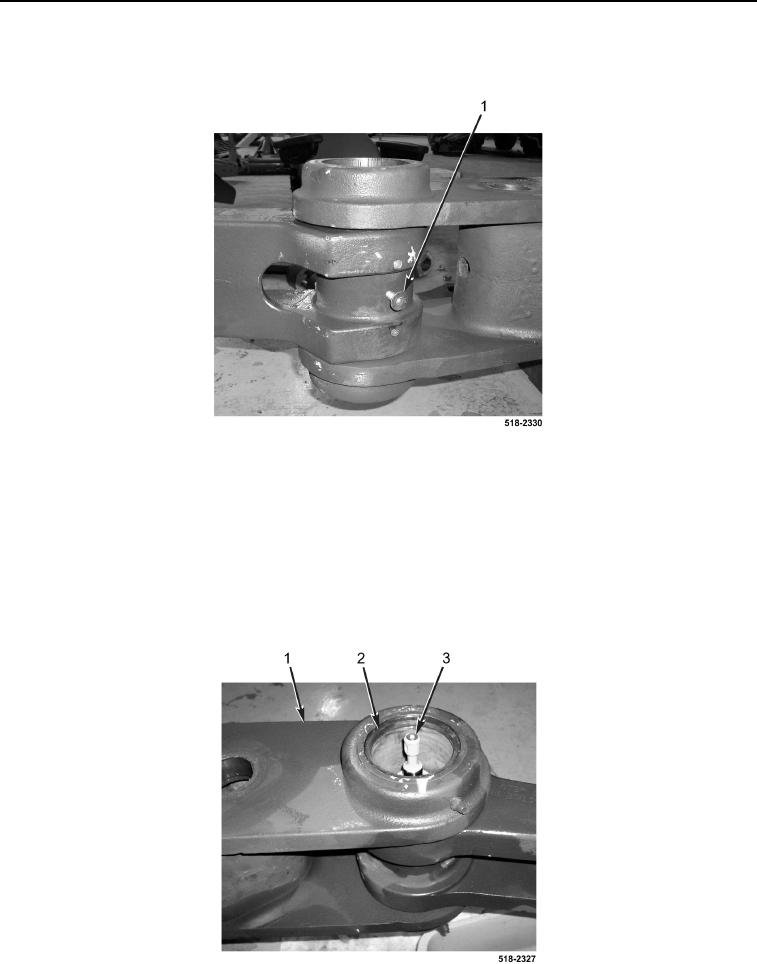
7. Insert bolt (Figure 14, Item 1) until flush with bushing to aid in alignment of cylinder.
Figure 14. Alignment Bolt.
0297
NOTE
Install coupler cylinder fittings and bushing in position and orientation noted during
removal.
8. Install coupler cylinder (Figure 15, Item 3) and coupler bushing (Figure 15, Item 2) on backhoe dipper support
arm (Figure 15, Item 1).
9. Remove bolt (Figure 14, Item 1).
Figure 15. Coupler Bushing and Cylinder.
0297