
TM 5-2420-231-23-3
0297
INSTALLATION CONTINUED
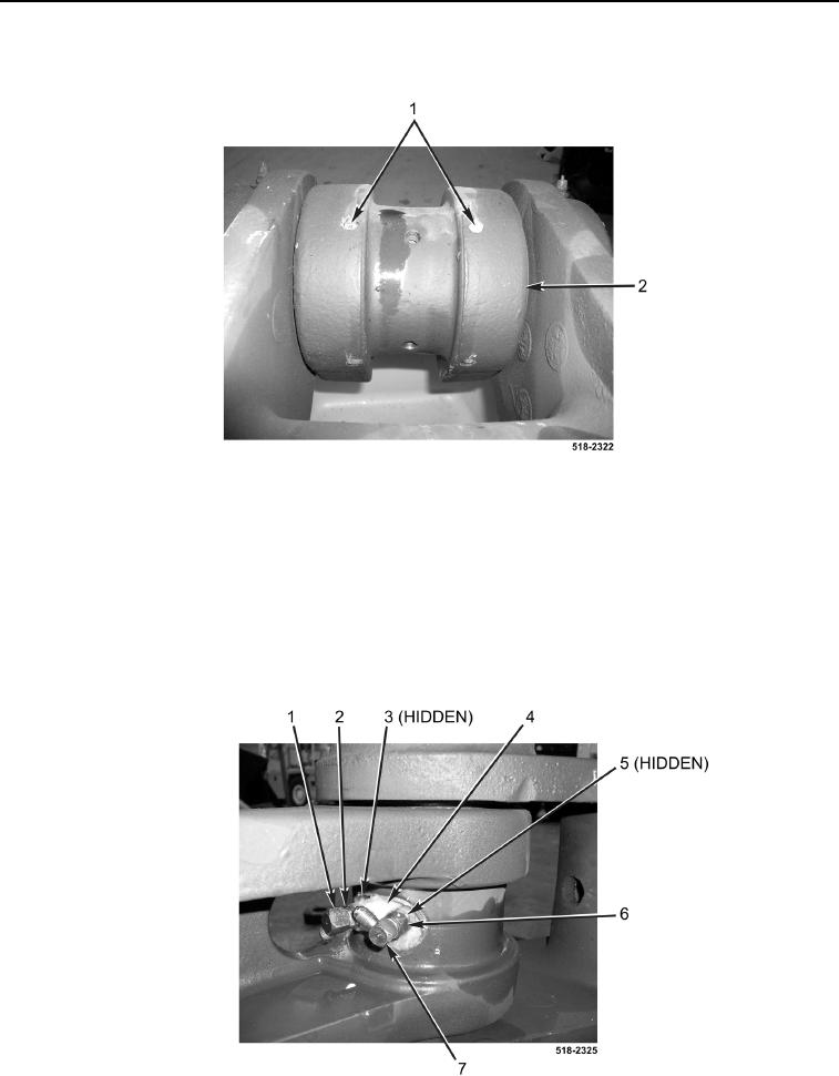
10. Install four set screws (Figure 16, Item 1) on cylinder (Figure 16, Item 2).
Figure 16. Set Screws.
0297
NOTE
Install fittings in position and location noted during removal.
11. Install new O-ring (Figure 17, Item 3) and fitting (Figure 17, Item 2) on coupler cylinder (Figure 17, Item 4).
12. Install new O-ring (Figure 17, Item 5) and fitting (Figure 17, Item 6) on coupler cylinder (Figure 17, Item 4).
13. Install 90-degree elbow (Figure 17, Item 1) on fitting (Figure 17, Item 2).
14. Install 90-degree elbow (Figure 17, Item 7) on fitting (Figure 17, Item 6).
Figure 17. Hydraulic Fittings.
0297