
TM 5-3805-255-14
0092
CLEANING AND INSPECTION CONTINUED
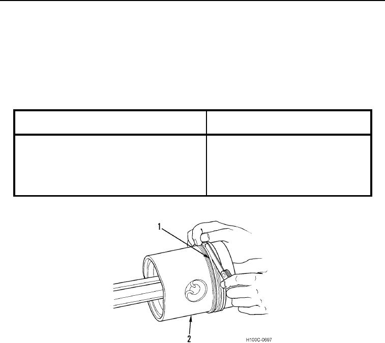
3. Check oil control ring as follows:
a. Inspect windows of oil control ring (Figure 5, Item 1) and piston (Figure 5, Item 2) for blocked oil-ways.
Failure to keep oil-ways clear will result in uneven lubrication and hot-spots on piston and cylinder sleeve.
b. With a feeler gauge, check side clearance of oil control ring (Figure 5, Item 1) in its groove. See Table 4 for
specifications.
Table 4. Oil Control Ring Specifications.
SPECIFICATION
in. (mm)
ITEM
092
092
Ring Side Clearance in Groove (New)
0.0019 to 0.0035 in. (0.048 to 0.089 mm)
Ring Side Clearance in Groove (Max)
0.0045 in. (0.114 mm)
Ring Gap
0.017 to 0.032 in. (0.43 to 0.81 mm)
Maximum Permissible Ring Gap (Before Replacing)
0.060 in. (1.52 mm)
Figure 5. Checking Oil Control Ring Side Clearance.
0092
0092-6