TM 5-3805-255-14
0092
CLEANING AND INSPECTION CONTINUED
NOTE
The following checks are made to ensure top compression ring fit is correct and not
carrying piston load.
c.
Install correct compression ring in top piston groove and be sure it is seated into groove.
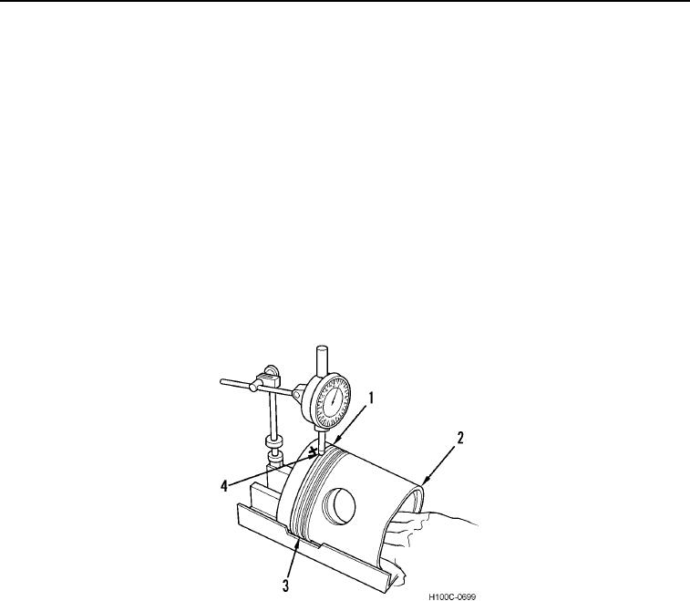
d. Position a dial indicator gauge on special service tool PLT-501 (Figure 7).
e. Position piston (Figure 7, Item 2) on tool with piston ring in clearance slot (Figure 7, Item 3) of tool, and
locate piston land directly above ring under indicator pointer (Figure 7, Item 4).
NOTE
IMPORTANT: Be sure that piston ring is seated in its groove.
f.
Set pointer at zero and slide piston forward (toward gauge) until pointer rests on ring. Note dial reading. It
must read 0.002 to 0.015 in. (0.05 to 0.38 mm) below piston land with pointer resting on top ring.
g. Repeat step (f) at four positions 90 degrees apart and be sure that all readings are within specifications.
Figure 7. Checking Piston Ring Drop.
0092
NOTE
When new rings are being installed on a used piston for operation in a used sleeve, wear
on sleeve may have left a ridge where piston reaches top of its stroke. This ridge will
cause noisy engine operation and breakage of top ring. Remedy this by removing ridge
with a ridge grinder before installing piston and ring.
0092-8

