
TM 5-3805-255-14
0092
CLEANING AND INSPECTION CONTINUED
NOTE
On a used piston, side clearances tend to increase toward top of piston due to greater
operating temperature prevalent at this point.
4. Check compression rings as follows:
a. Check compression ring grooves using a new keystone ring to correctly establish piston groove wear.
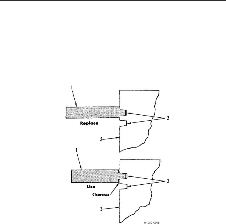
b. Obtain a Perfect Circle piston ring gauge No. 1 (1/8 in. by 15 degrees) (Figure 6, Item 1) and insert it in ring
groove (Figure 6, Item 2). If one or both shoulders on gauge touch ring groove land (Figure 6, Item 2),
piston (Figure 6, Item 3) must be replaced. A groove worn this much would not support ring in operating
position. Install a new piston and rings.
Figure 6. Checking Piston Compression Ring Grooves.
0092
0092-7