
TM 5-3805-255-14
0102
CLEANING AND INSPECTION
000102
Cleaning
000102
Clean all metal parts IAW General Maintenance Instructions (WP 0019) in cleaning solvent and dry with
compressed air. Lubricate all machined surfaces with clean machine oil (WP 0131). During cleaning operation, pay
particular attention to oil passages, bearing assemblies, bearing bores, snap and seal ring grooves, and screw
threads.
Inspection
000102
Inspect all parts for wear or damage. Check converter and rotating housings for cracks. Inspect bearing bores and
mounting faces for wear, grooves, or scratches. Remove burrs and scratches with a crocus cloth. Inspect all
splined parts for worn, twisted, chipped, or burred splines. Remove burrs with a soft stone. Check turbine, impeller,
and guide wheel for cracks or other damage. Replace any parts that are in doubt or cannot be repaired.
END OF TASK
ASSEMBLY
000102
NOTE
Make sure all components are properly seated during assembly.
The ground sleeve hub must be chilled for at least 30 minutes prior to assembly.
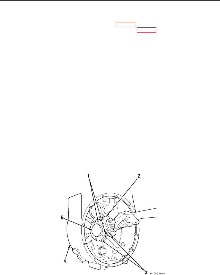
1. Place converter housing (Figure 24, Item 4) in a press with output side down.
2. Position new gasket in housing.
CAUTION
Ensure oil passages (Figure 24, Item 3) are aligned. Failure to follow procedures may
cause damage to equipment.
3. Install ground sleeve hub (Figure 24, Item 2) and position hub in converter housing (Figure 24, Item 4).
Figure 24. Ground Sleeve Hub Installation.
0102
0102-15