• Home
  • Download PDF
  • Order CD-ROM
  • Order in Print
Figure 12. Pitman Arm Shaft Installation.
Figure 16. Steering Gear Assembly.

Maintenance Manual For Loader, Scoop Type, Ded 4 X 4, Articulated Frame Steer, 4.5 To 5 Cu. Yd.
Page Navigation
  1199    1200    1201    1202    1203  1204  1205    1206    1207    1208    1209  
img
TM 5-3805-255-14
0116
ASSEMBLY CONTINUED
15. Install side cover (Figure 14, Item 2) on spur shaft (Figure 14, Item 1).
Figure 14. Pitman Shaft Installation.
0116
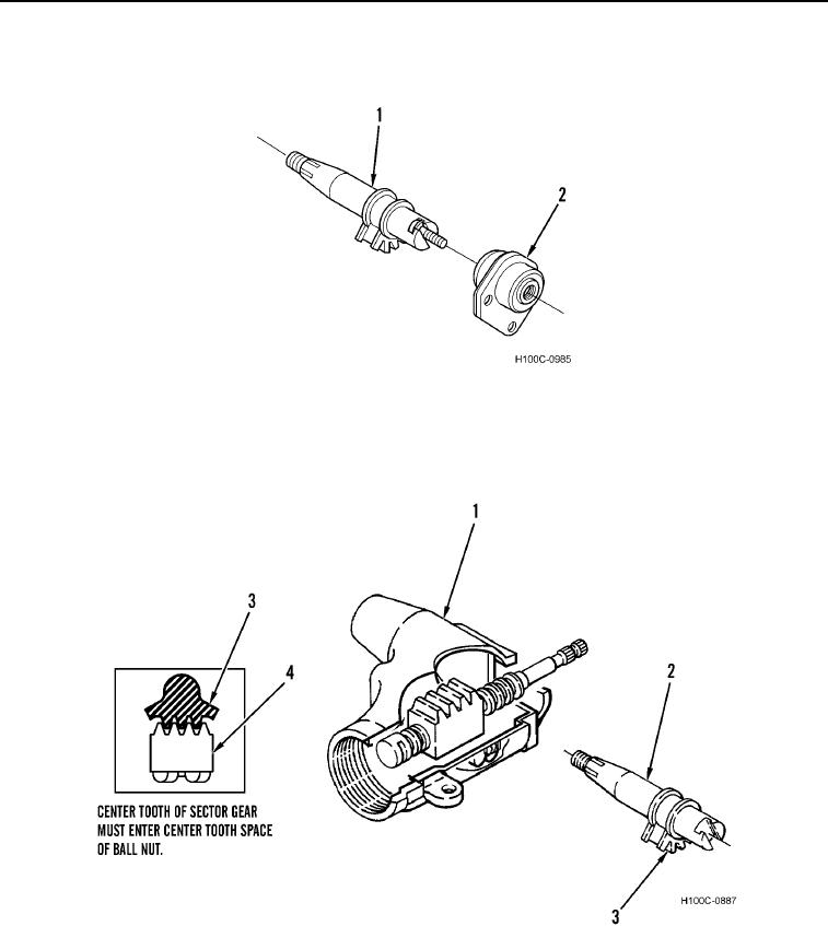
16. Install spur shaft (Figure 15, Item 2) into housing (Figure 15, Item 1).
17. Ensure spur shaft teeth (Figure 15, Item 3) and ball nut (Figure 15, Item 4) are properly aligned.
Figure 15. Ball Nut Gear Alignment.
0116
0116-11


Privacy Statement
Press Release
Contact

© Copyright Integrated Publishing, Inc.. All Rights Reserved.