
TM 5-3805-255-14
0116
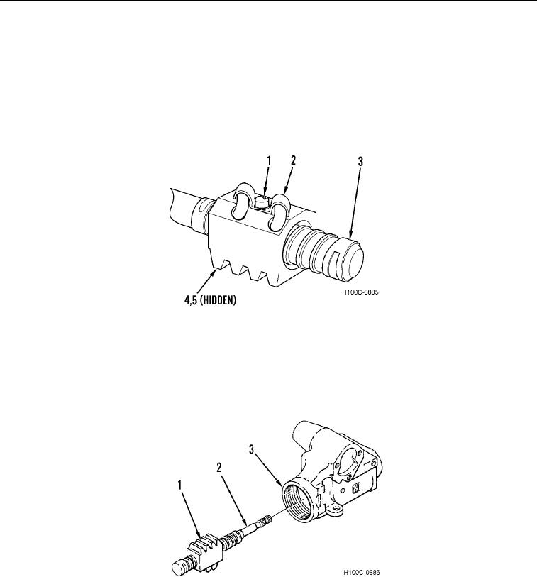
ASSEMBLY CONTINUED
8. Install ball return guide clamp (Figure 10, Item 2) on ball nut (Figure 10, Item 4).
9. Install screw (Figure 10, Item 1) through guide clamp (Figure 10, Item 2) in ball nut (Figure 10, Item 4). Tighten
screw securely.
10. Make sure ball nut (Figure 10, Item 4) and balls (Figure 10, Item 5) are thoroughly lubricated. Test assembly by
rotating ball nut on worm shaft (Figure 10, Item 3). Do not rotate ball nut to end of worm shaft threads.
Assembly must move freely. Temporarily tape worm shaft at both ends of ball nut until ready to be installed
during assembly.
Figure 10. Ball Guide Fastener Installation.
0116
11. Remove tape from worm shaft (Figure 11, Item 2). Secure ball nut (Figure 11, Item 1) in place on shaft (Figure
11, Item 2).
12. Insert worm shaft (Figure 11, Item 2) in gear housing (Figure 11, Item 3).
Figure 11. Worm Shaft Installation.
0116
0116-9