
TM 5-3805-255-14
0116
ASSEMBLY CONTINUED
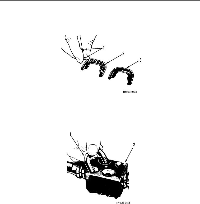
5. Lay half of ball guide (Figure 8, Item 2) groove up, on bench. Place remaining balls (Figure 8, Item 1) in groove
of guide. Cover assembly with opposite half of guide (Figure 8, Item 3). Hold two halves together and plug
each end with technical petrolatum to prevent balls from dropping out while installing guide.
Figure 8. Ball and Guide Assembly.
0116
6. Push ball return guide (Figure 9, Item 1) completely in holes on ball nut (Figure 9, Item 2). If guide does not
push down all the way easily, tap it lightly into place. This completes one circuit of balls.
7. Fill remaining circuit with balls in the same manner described in step 6.
Figure 9. Ball Guide Installation.
0116
0116-8