
TM 5-3805-255-14
0116
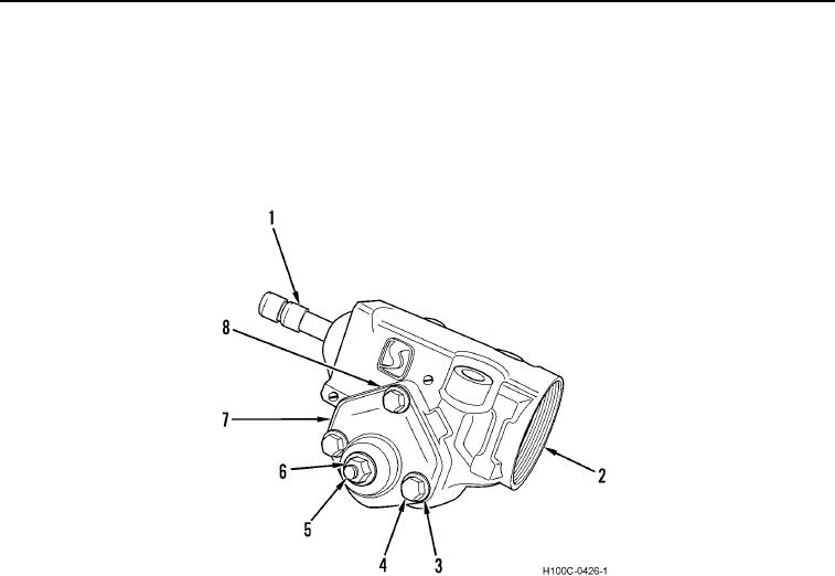
ASSEMBLY CONTINUED
18. Install new gasket (Figure 16, Item 8) and side cover (Figure 16, Item 7) on housing (Figure 16, Item 2).
19. Back off adjuster screw to permit lash (play) between spur shaft and ball nut on worm shaft (Figure 16, Item 1).
20. Install three side cover bolts (Figure 16, Item 4) with new lockwashers (Figure 16, Item 3) and tighten to 25 to
40 lb-ft (34 to 54 Nm) torque.
21. Install nut (Figure 16, Item 6) on adjuster screw (Figure 16, Item 5).
Figure 16. Steering Gear Assembly.
0116
0116-12