
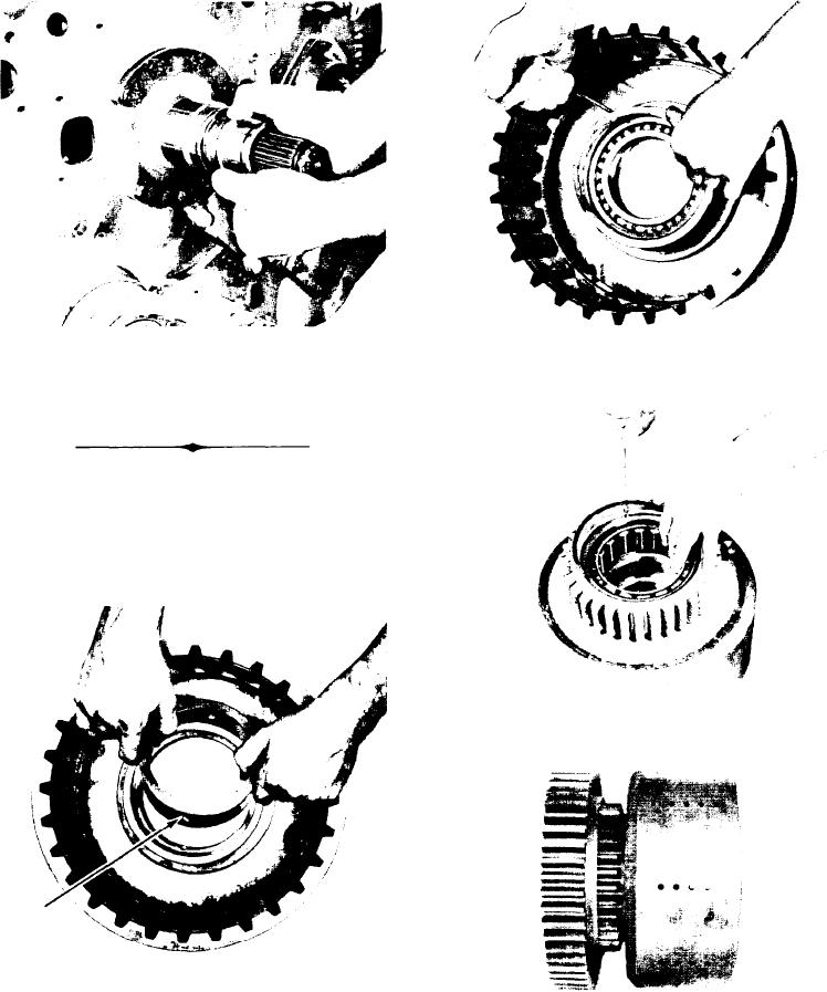
Figure 102
Figure 104
Install new clutch support piston rings. lock rings in
Press support ball bearing in clutch drum, and secure
position. Lubricate piston rings with automatic trans-
with bearing retainer ring.
mission fluid.
REASSEMBLY OF CLUTCHES
NOTE: All clutches are assembled in a similar manner.
The quantity of clutch discs will differ between the
1st and 2nd clutch and the forward, reverse, 3rd, and
4th. Do not mix 1st and 2nd clutch plates with for-
ward, reverse, 3rd, and 4th.
Figure 105
From rear end of clutch drum, press support roller
bearing in drum, secure with retainer ring.
Figure 103
Insert lock ball in clutch piston ring outer race. Press
Figure 106
outer race and ball in clutch drum. Outer race must
Press clutch drum hub gear on clutch drum with longer
b e pressed from flush to 1/64" [0,41mm] below
offset of gear hub inward. NOTE: clutch drum hub
shoulder in clutch drum.
gear is used only on the 1st and 2nd clutch.
-37-