E N G I NE
E L E C T R I C A L S Y S T EM
TM 5-3805-258-24-1
S Y S T E M S O P E R A T I O N
T Y P I C A L S O L E N O I D S C H E M A T I C
The solenoid switch is made of an electromagnet
(one or two sets of windings) around a hollow cy-
linder. There is a plunger (core) with a spring load
inside the cylinder that can move forward and back-
ward. When the start switch is closed and electricity
is sent through the windings, a magnetic field is made
that pulls the plunger forward in the cylinder. This
moves the shift lever (connected to the rear of the
plunger) to engage the pinion drive gear with the ring
gear. The front end of the plunger then makes con-
tact across the battery and motor terminals of the
solenoid, and the starter motor begins to turn the
flywheel of the engine.
When the start switch is opened, current no longer
flows through the windings. The spring now pushes
the plunger back to the original position, and, at the
same time, moves the pinion gear away from the
flywheel.
When two sets of windings in the solenoid are used,
they are called the hold-in winding and the pull-in
winding. Both have the same number of turns around
the cylinder, but the pull-in winding uses a larger
diameter wire to produce a greater magnetic field.
When the start switch is closed, part of the current
flows from the battery through the hold-in winding,
and the rest flows through the pull-in windings to
motor terminal, then through the motor to ground.
When the solenoid is fully activated (connection
across battery and motor terminal is complete), cur-
rent is shut off through the pull-in windings. Now
only the smaller hold-in windings are in operation for
the extended period of time it takes to start the
engine. The solenoid will now take less current from
the battery, and heat made by the solenoid will be
kept at an acceptable level.
Starter Motor
The starter motor is used to turn the engine fly-
wheel fast enough to get the engine to start running.
The starter motor has a solenoid. When the start
switch is activated, the solenoid will move the starter
pinion to engage it with the ring gear on the flywheel
of the engine. The starter pinion will engage with the
ring gear before the electric contacts in the solenoid
close the circuit between the battery and the starter
motor. When the circuit between the battery and the
starter motor is complete, the pinion will turn the
engine flywheel. A clutch gives protection for the
starter motor so that the engine can not turn the
starter motor too fast. When the start switch is re-
leased, the starter pinion will move away from the
ring gear.
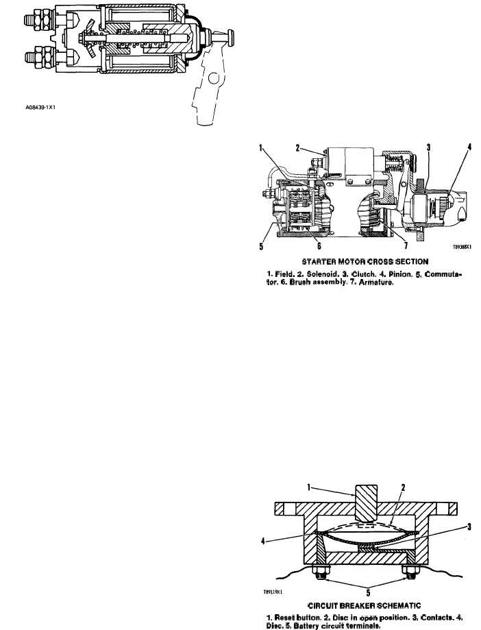
STARTER MOTOR CROSS SECTION
1. Field. 2, Solenoid. 3. Clutch. 4. Pinion. 5, Commuta-
tor. 6. Brush assembly. 7. Armature.
OTHER COMPONENTS
Circuit Breaker
The circuit breaker is a switch that opens the
battery circuit if the current in the electrical system
goes higher than the rating of the circuit breaker.
A heat activated metal disc with a contact point
makes complete the electric circuit through the cir-
cuit breaker. If the current in the electrical system
gets too high, it causes the metal disc to get hot. This
heat causes a distortion of the metal disc which opens
the contacts and breaks the circuit. A circuit breaker
that is open can be reset (an adjustment to make the
circuit complete again) after it becomes cool. Push
the reset button to close the contacts and reset the
circuit breaker.
CIRCUIT BREAKER SCHEMATIC
1. Reset button. 2. Disc in open position. 3. Contacts. 4.
Disc. 5. Battery circuit tarminals.
3-19