P O W E R T R A IN
TM 5-3805-258-24-1
S Y S T E M S O P E R A T I O N
TORQUE CONVERTER
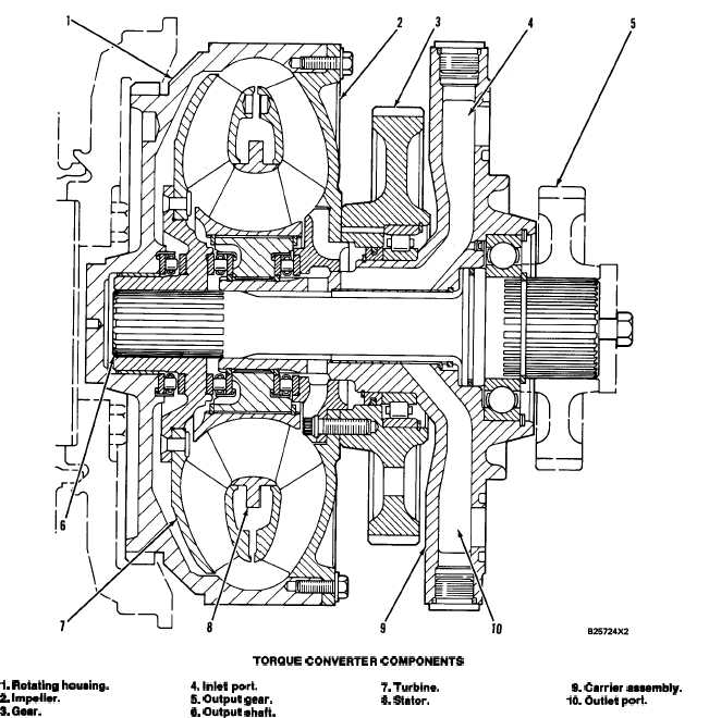
TORQUE CONVERTER COMPONENTS
l. Rotating housing.
4.inlet port.
7. Turbine.
2 Impeller.
9. Carrier aaaembly.
5. Output gear.
8. Stator.
10. Outlet port.
3. Gear.
8. Output aheft.
The torque converter is located at the input end of
cold. It is part of the selector and pressure control
the transmission. The converter housing is bolted to
valve group in the transmission hydraulic controls.
the flywheel housing. Output torque from the con-
verter enters the planetary transmission through
The outlet oil pressure is controlled by the relief
either the No. 1 or No. 2 sun gear. The gear that
valve for torque converter outlet. This valve is
receives the output, is dependent upon the directional
mounted on the right side of the converter cover and
clutch engaged.
does not allow converter outlet pressure to go above
Oil for the operation of the converter is supplied by
415 kPa (60 psi).
the transmission oil pump. The converter inlet oil
pressure is controlled by the ratio valve for the torque
Rotating housing (1), impeller (2), and oil pump
converter. This valve limits the pressure to the con-
drive gear (3) are driven by the flywheel and rotate
verter to 965 kPa (140 psi) maximum when the oil is
as a unit at engine speed.
3-21


