TM 5-3805-258-24-1
POWER TRAIN
GENERAL INFORMATION
S Y S T E M S O P E R A T I O N
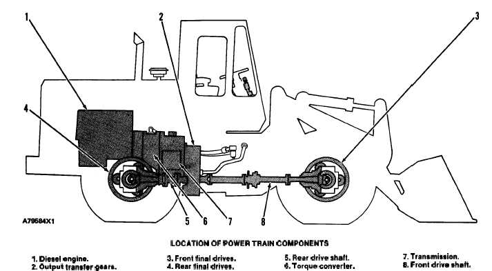
LOCATION OF POWER TRAIN COMPONENTS
1. Diesel engine.
3. Front final drives.
5. Rear drive shaft.
7. Transmission.
2. Output tranafer geara.
4. Rear final drives.
6. Torque converter.
8. Front drive shaft.
Power from diesel engine (1) is sent from the
flywheel to torque converter (6). The torque con-
verter output gear is connected to the transmission
input gear.
Six hydraulically activated clutches in the trans-
mission, give four forward speeds and four reverse
speeds. Speed and direction selections are made
manually.
The transmission output shaft is connected to a
gear in the output transfer gear case by splines.
Power is sent through the gear to the output gear.
The output gear sends power through drive shaft (5)
to the rear drive pinion. The output gear also sends
power to the front drive pinion through drive shaft
(8).
The pinions, bevel gears and gears of each differ-
ential turn their respective axles. The axles are con-
nected to final drives (3) and (4). The final drives
turn the wheels.
3-20