TM 5-3805-258-24-1
A I R S Y S T E M A N D B R A K E S
S Y S T E M S O P E R A T I O N
AIR CIRCUIT FOR THE EMERGENCY AND PARKING BRAKE
engaged. The transmission control lever must be held
in position, with a much higher force than normal, to
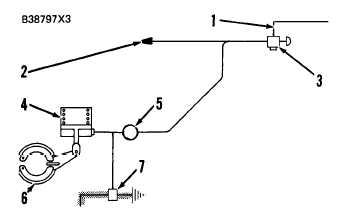
A I R C I R C U I T F O R T H E E M E R G E N CY
A N D P A R K I N G B R A KE
1. Line from left brake control valve. 2. Line to transmis-
s i o n n e u t r a l i z e r g r o u p . 3 . C o n t r o l v a l v e f o r e m e r g e n c y
and parking brake. 4. Brake chamber for emergency and
parking brake. 5. Quick release valve. 6. Emergency and
parking brake. 7. Air pressure switch.
The components of the air circuit for the emer-
gency and parking brake are a control valve, an
air pressure switch, a quick release valve, a brake
chamber and a brake.
Air pressure (from the left brake control valve)
goes to control valve (2), which controls the opera-
tion of brake chamber (6). When air pressure is
sent to the brake chamber, emergency and parking
brake (7) is disengaged (released). When air pres-
sure to the brake chamber is released, a spring in
the brake chamber engages (activates) the emer-
gency and parking brake.
Quick release valve (8) decreases the time it takes
to engage emergency and parking brake (7). The
air is released at the quick release valve instead of
at control valve (2).
Switch (4) activates the warning system in the
operator’s station when the parking brake control
knob is in the ON position.
The emergency and parking brake is used to stop
the machine in an emergency when the machine is in
operation. It is also used as a parking brake when the
machine is not in operation. Brake (7) is activated
automatically when the air pressure goes below 275
kPa (40 psi). When the parking brake is activated,
the transmission is automatically shifted into neutral.
The transmission neutralizer group prevents dam-
age to the parking brake when the parking brake is
activated. The machine can be moved, in an emer-
gency, a very short distance with the parking brake
3-74
move the machine in this condition.
CAUTION
The machine can only be moved a very short
distance with the parking brake engaged or the
brake will be destroyed.
CONTROL VALVE FOR THE EMERGENCY
AND PARKING BRAKE
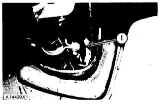
Control valve (1) for the emergency and parking
brake is fastened to the lower end of the steering
column. The valve is activated either manually or
automatically. The valve is controlled manually by a
cable assembly that is connected to knob (2) on the
upper end of the steering column. The valve is acti-
vated automatically when pressure in the air system
is too low.
L O C A T I O N O F T H E C O N T R O L V A L VE
1. Control valve.
When the machine is started, the air reservoir will
be discharged. The control valve will be in the ON
position (pulled out). Valve (9) will be against valve
body (4). The air can not go through outlet port (7)
or exhaust port (11). The air pressure in the reservoir
will go up to the correct pressure for operation.


