TM 5-3805-258-24-1
A I R S Y S T E M A N D B R A K E S
S Y S T E M S
O P E R A T I ON
AIR CIRCUIT FOR THE WHEEL BRAKES
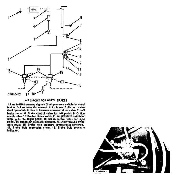
AIR CIRCUIT FOR WHEEL BRAKES
1. Line to EMS warning signals. 2. Air pressure switch for wheel
brakes. 3. Line from air reservoir. 4. Air horns. 5. Atr horn valve
(foot operated). 6. Line to transmission neutralizer valve. 7, Left
brake pedal. 8. Brake control valve for left pedal. 9. Orifice
check valve. 10. Double check valve. 11. Air pressure switch for
stop lights. 12. Right pedal. 13. Brake control valve for right
pedal. 14. Brake air pressure indicator. 15. Air/hydraulic cylin-
ders (two). 16. Brake fluid pressure (overstroke) switches.
17.
Brake fluid reservoirs (two). 18. Brake fluid pressure
indicator.
The air circuit for the wheel brakes sends air under
pressure from the air reservoir to operate the air/hy-
draulic cylinders and the air horns.
Switch (2) activates the warning system in the
operator’s station when air pressure in the system
is too low.
Horn valve (5) activates air horn (4).
When left brake control valve (8) is activated, the
wheel brakes engage and the transmission neutralizer
valve is activated. The transmission neutralizer valve
stops oil pressure to the directional clutch circuit,
which disengages the directional clutch. Since a speed
and direction clutch must both be engaged before pow-
er goes through the transmission, power does not go
through the transmission when the left brake pedal is
pushed. The surface area of the neutralizer valve is
smaller than the surface area of the air cylinder piston.
This difference in area causes the transmission to dis-
engage before the wheel brakes are engaged.
When control valve (8) is released, orifice check
valve (9) causes a restriction to the flow of air from
the air cylinders to brake control valve (8). This
permits the transmission to engage before the
brakes are released.
Air pressure from the orifice check valve goes to
double check valve (10). Valve (10) lets air go to
the air cylinders and will not let air go to control
valve (13). When control valve (13) is activated,
valve (10) lets air go to the air cylinders and will
not let air go to valve (9).
Right brake control valve (13) activates the
wheel brakes only. When either control valve (8)
or (13) is activated, stop light switch (11) activates
the stop lights at the rear of the machine.
Air/hydraulic cylinders (15) have two cylinders
each, one for air (air cylinder) and one for brake
fluid (master cylinder). Movement of the air cyl-
inder is caused by air pressure. This movement also
causes the master cylinder to move and the wheel
brakes are activated. The master cylinder is part
of the hydraulic circuit for the wheel brakes.
AIR PRESSURE SWITCH FOR
WHEEL BRAKES
L O C A T I O N O F T H E A I R P R E S S U R E S W I T CH
1. Switch.
Air pressure switch (1) is activated when the air
pressure in the brake system gets below approximately
450 kPa (65 psi). The switch causes the brake air pres-
sure indicator and the master fault light in the dash to
come ON, and also the fault alarm will sound.
Switch (1) is under the floor of the operator’s station.
It is fastened to the left brake control valve.
3-79