TM 5-3805-258-24-1
A I R S Y S T E M A N D B R A K E S
A I R C I R C U I T F O R T H E E M E R G E N C Y
A N D P A R K I N G B R A K E
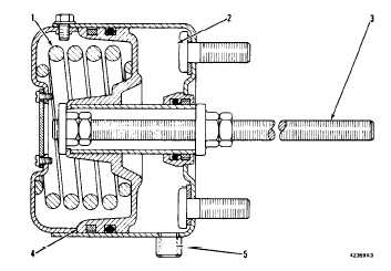
B R A K E C H A M B E R I N R E L E A S E D P O S I T I ON
1. Spring. 2. Air chamber. 3. Brake chamber rod. 4. Pis-
ton. 5. Air inlet.
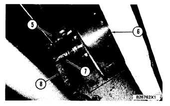
L O C A T I O N O F B R A K E C H A M B ER
5. Air inlet. 6. Brake chamber. 7. Rod end. 8. Lever.
The brake stays activated until the air system is at
the correct pressure for operation and the parking
and emergency brake control valve is moved to the
OFF position (knob is pushed in). At this time, air
pressure goes to air chamber (2) and pushes piston
(4) to the left. Rod (3) and rod end (7) move lever (8)
which releases the emergency and parking brake.
When air pressure decreases to approximately 275
kPa (40 psi), the parking and emergency brake con-
trol valve closes automatically (moves to the ON
position) and stops the flow of air to air chamber (2).
Spring (1) is no longer in compression and pushes rod
(3) out and the brake is activated (emergency
brakes).
This same operation takes place when the parking
and emergency brake control valve is manually
moved to the ON position (pulled out). This activates
the brake for parking.
S Y S T E M S
O P E R A T I O N
EMERGENCY AND PARKING BRAKE
The emergency and parking brake is fastened to
the loader frame. Brake drum (4) is fastened to a
yoke on the front drive shaft. The brake is a shoe-type
brake that is engaged and released by brake chamber
(1) for the emergency and parking brake.
Plate (6) is fastened to the bearing housing for the
front drive shaft. The plate is stationary and holds
shoes (8) and the rest of the brake components in
position.
When the emergency and parking brake control
knob is in the OFF position, air pressure in the brake
chamber causes rod end (2) and lever (3) to move in
the direction shown. Lever (3), connected to cam-
shaft (5), causes the camshaft to turn in a counter-
clockwise direction. Camshaft (5) is now not in con-
tact with shoes (8) and the shoes are not in contact
with brake drum (4). The brake is released.
When the control knob is moved to the ON posi-
tion, air pressure in the brake chamber is released.
The springs in the brake chamber push rod end (2)
out and lever (3) turns camshaft (5) in a clockwise
direction. The camshaft comes in contact with shoes
(8) and pushes them against brake drum (4). The
brake is now engaged.
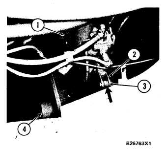
L O C A T I O N O F E M E R G E N C Y A N D P A R K I N G B R A K E
1. Brake chamber. 2. Rod end. 3. Lever. 4. Brake drum.
3-77