TM 5-3805-258-24-1
A l R S Y S T E M A N D B R A K ES
S Y S T E M S
O P E R A T I O N
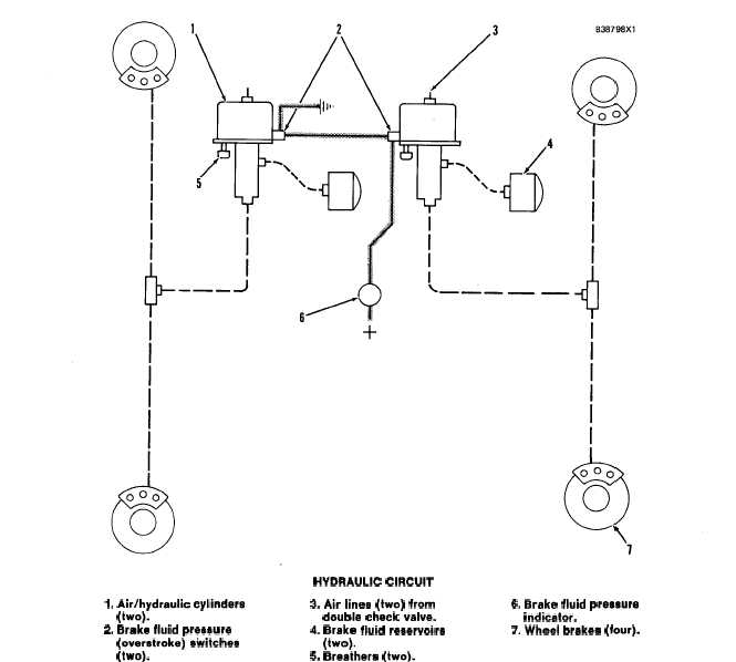
HYDRAULIC CIRCUIT FOR THE WHEEL BRAKES
1. Air/hydraulic cylinders
(two).
2. Brake fluid preaaure
(overatroke) eivitchea
(two).
HYDRAULIC CIRCUIT
3. Air Iinee (two) from
6. Brake fluid preaaure
double check valve.
indicator.
4. Brake fluid reaervoira
7. Wheel brakea (four).
(two).
5. Breathere (two).
The hydraulic circuit is divided into two separate
circuits, one for the front wheel brakes and one for
the rear wheel brakes. Each circuit has a reservoir, an
air/hydraulic cylinder and two wheel brakes.
Air/hydraulic cylinders (1) have two cylinders
each, one for air (air cylinder) and one for brake fluid
(master cylinder). The air cylinders are part of the
air circuit for the wheel brakes. Air pressure in the
air cylinders moves the piston in the master cylinder,
which causes the compression of the brake fluid in
the hydraulic circuit and activates the brakes.
Wheel brakes (7) are at all four wheels. They are
used to stop the movement of the machine during
normal operation.
Brake fluid pressure (overstrike) switches (2) acti-
vate brake fluid pressure indicator (6) when there is
too much travel (stroke) in the master cylinder.
NOTE: All parts in the hydraulic circuit are for use
with DOT 3 brake fluid only.
Reservoirs (4) provide extra brake fluid for the
master cylinders.
3-85