TM 5-3805-258-24-1
A I R S Y S T E M A N D B R A K E S
A I R C I R C U I T F O R T H E
W H E E L B R A K ES
S Y S T E M S
O P E R A T I O N
Operation
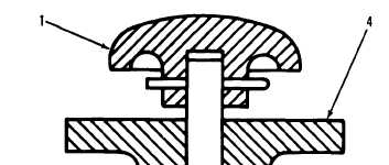
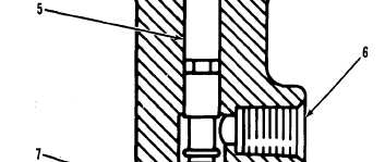
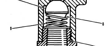
When button (1) is pushed, stem (5) pushes valve
(7) against the force of spring (9). This lets air
pressure from inlet passage (10) go to outlet passage
(6) and to air horns (3).
C O M P O N E N T S O F T H E H O R N V A L VE
1. Button. 4. Valve body. 5. Stem. 6. Outlet. 7. Valve. 8.
Spring seat. 9. Spring. 10. Inlet.
When button (1) is released, spring (9) moves
valve (7) back to its seat in valve body (4). This stops
the flow of air to outlet passage (6). The horns are
OFF. Spring seat (8) holds spring (9) in the correct
position.
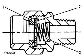
ORIFICE CHECK VALVE
The orifice check valve is fastened directly to an
elbow that is connected to the double check valve on
the brake control valve for the right pedal.
When the brake control valve for the left pedal is
activated, air pressure moves valve (2) to the right
against the force of spring (3). Air is permitted to
flow freely through notches on the outside diameter
of valve (2). Some air will also go through the orifice.
This flow of air is to the air cylinders.
When the left pedal is released, the orifice causes a
restriction to the flow of air from the air cylinders to
the brake control valve. This permits the transmis-
sion to engage before the brakes are released.
C O M P O N E N T S O F T H E O R I F I C E C H E C K V A L V E
1. Seat. 2. Valve. 3. Spring.
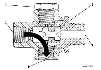
DOUBLE CHECK VALVE
The double check valve is fastened directly to the
brake control valve for the right pedal. Inlet passage
(4) is connected to the brake control valve. An elbow,
from the orifice check valve, is installed in inlet pas-
sage (3).
Shuttle (2) keeps air pressure from movement to
the right brake control valve, when the left brake
control valve is activated. When the right control
valve is activated, shuttle (2) keeps air pressure from
movement to the left control valve, which would
permit the transmission to disengage.
D O U B L E C H E C K V A L VE
1 . P l u g . 2 . S h u t t l e . 3 . I n l e t p a s s a g e f r o m l e f t c o n t r o l
valve. 4. Inlet passage from right control valve. 5. Outlet
to air cylinders.
Shuttle (2) moves when inlet pressures are differ-
ent. The shuttle opens the inlet passage with the
3-82

