A I R S Y S T E M A N D B R A K E S
A I R C I R C U I T F O R T H E
W H E E L B R A K E S
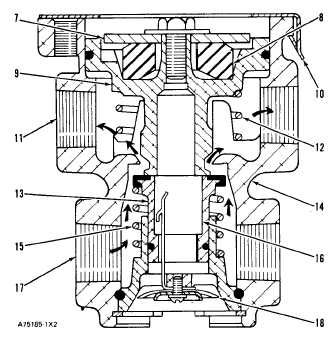
sage (16) and out exhaust diaphragm (18) until the
forces above and below piston (9) are in balance.
When the pedal is completely released, piston (9)
moves off of valve (13). This completely releases all
pressure in the system. Valve (13) is held against
valve body (14) by spring (15).
B R A K E C O N T R O L V A L V E ( B r a k e s A c t i v a t e d )
7. Seat. 8. Rubber spring. 9. Piston. 10. Retainer. 11. Out-
l e t p a s s a g e . 1 2 . S p r i n g . 1 3 . V a l v e . 1 4 . V a l v e b o d y . 1 5 .
Spring. 16. Exhaust passage. 17. Inlet passage. 18. Ex-
h a u s t d i a p h r a g m .
The operation of valves (3) and (4) is the same.
In valve (4), outlet passage (11) goes to the air cyl-
inders only. In valve (3), outlet passage (11) goes
to the air cylinders and the transmission neutralizer
valve.
AIR HORNS AND VALVE
TM 5-3805-258-24-1
S Y S T E M S O P E R A T I O N
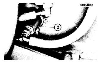
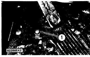
Air horns (3) are activated by horn valve (2). The
horn valve is activated (foot-operated) by horn
button (1). The air horns are under the right hand
platform. Horn valve (2) is fastened directly under
the floor of the operator’s station.
T Y P I C A L L O C A T I O N O F T H E H O R N V A L VE
2. Valve.
L O C A T I O N O F T H E A I R H O R NS
3. Horns.
L O C A T I O N O F H O R N B U T T ON
1. Button.
3-81


