TM 5-3805-258-24-1
H Y D R A U L I C S Y S T E M
S Y S T E M S O P E R A T I O N
HYDRAULIC SYSTEM
INTRODUCTION
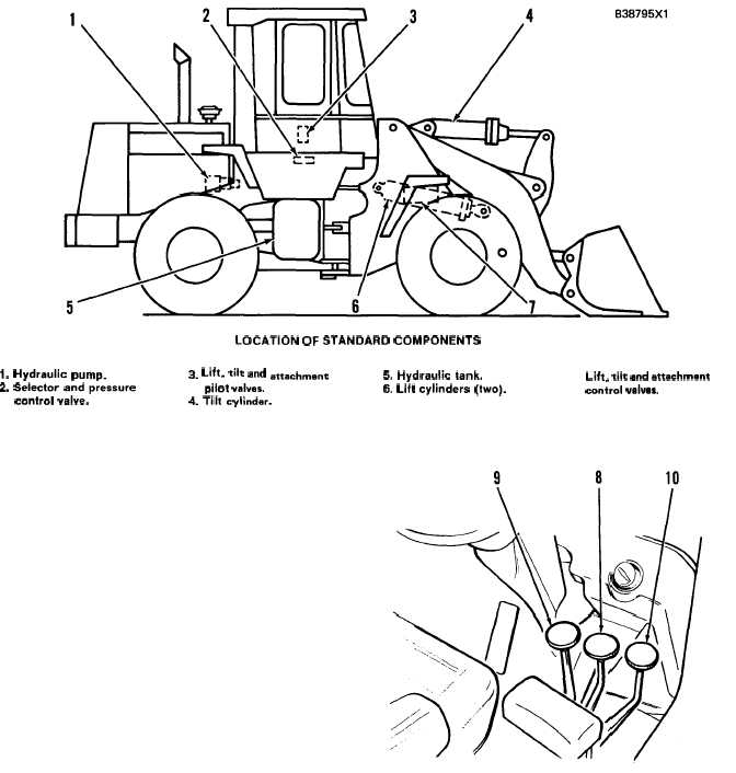
LOCATION OF STANDARD COMPONENTS
1. Hydraulic pump.
3. Lift, tik and attachment
5. Hydraulic tank.
2. Selector andpresaure
pilot valves.
6. Lift cylinders (two).
control valve.
4. Tilt cylinder.
The implement hydraulic system controls the
operation of the bucket and attachment (log fork,
side dump or multi-purpose bucket, etc.). There
are two separate oil systems in the implement
hydraulic system: pilot oil system and main
(implement) oil system. The implement oil system
is controlled by the pilot oil system. The standard
implement hydraulic system has a hydraulic pump
(1), hydraulic tank (5) with oil filters, selector and
pressure control valve (2), lift and tilt pilot valve
(3), lift and tilt (two spool) control valve (7), con-
trol linkage with electrical bucket positioner and
lift kickout, tilt cylinder (4) and lift cylinders (6).
The implement hydraulic system, in addition
to these components, has an attachment (third)
pilot valve, attachment (three spool control valve,
sequence valve,
shuttle valve and attachment
cylinders. To control the attachment, an additional
control lever (10) is added in the operator’s station.
This third lever is to the right of lift control lever
Lift, tilt and attachment
control valvea.
(8).
The hydraulic system is an open center, pilot
operated circuit. The flow of oil through the sys-
tem is not completely continuous. Hydraulic pump
CONTROL LEVERS
(1) for the hydraulic system is a three section
8. Lift control lever.
9. TiIt control lever.
10. Attachment
pump (implement, steering and pilot).
control lever.
3-89