TM 5-3805-258-24-1
A I R S Y S T E M A N D B R A K ES
H Y D R A U L I C C I R C U I T F O R T HE
W H E E L
B R A K ES
S Y S T E M S O P E R A T I O N
WHEEL BRAKES
Fluid goes through passages between the bores
of pistons (4). Fluid then goes between bores that
are opposite each other through a passage inside
head assembly (1).
WHEEL BRAKE
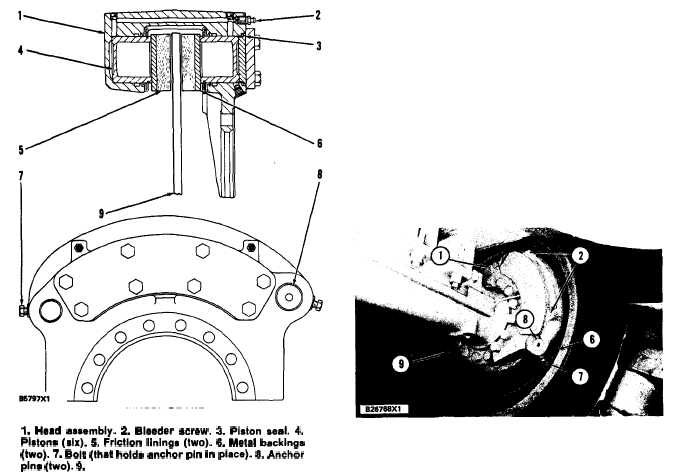
1. Head assembly. 2. Bleeder screw. 3. Piston saal. 4.
Pistons (six). 5. Friction linings (two). 6. Matal backings
(two). 7. Bolt (that holds anchor pln in placa). 8. Anchor
pins (two). 9. D i s c .
Fluid activated caliper/disc brakes are at all
four wheels. Head assembly (1) is fastened to the
axle flange and does not turn with the wheels. The
head assembly has six pistons (4), three on each
side of the disc, and a friction lining (5) on each
side of the disc. Each lining is fastened to a metal
backing (6). Linings (5) and backings (6) are held
in place by anchor pins (8). When the brakes are
activated, oil pushes pistons (4) and linings (5)
against these discs.
When the brakes are activated, the hydraulic
(brake fluid) pressure moves all pistons (4) and the
amount of force on each side of discs (9) is the
same. The pistons do not have springs for return.
NOTE: It is not necessary to remove head assem-
bly (1) to remove linings (5) and metal backings (6).
Remove bolts (7) and anchor pins (8). Remove the
linings and metal backings.
RIGHT FRONT WHEEL BRAKE
1. Head assembly. 2. Bleeder screws. 6. Metal backing.
7. Bolt. 8. Anchor pin. 9. Disc.
CAUTION
Do not activate the brakes with linings (5)
removed. Pistons (4) must not come out of
their bores when the linings are removed.
Open bleeder screws (2) to release any pres-
sure behind the pistons. If the pistons become
extended and the seals can be seen, removal
of the head assembly is necessary to install
the pistons again.
CAUTION
Do not activate brakes when the linings are
removed or pistons (4) and seals (3) will be
damaged.
3-88