TM 5-3805-258-24-1
A I R S Y S T E M A N D B R A K ES
A I R C I R C U I T F O R T H E
W H E E L B R A K E S
S Y S T E M S O P E R A T I O N
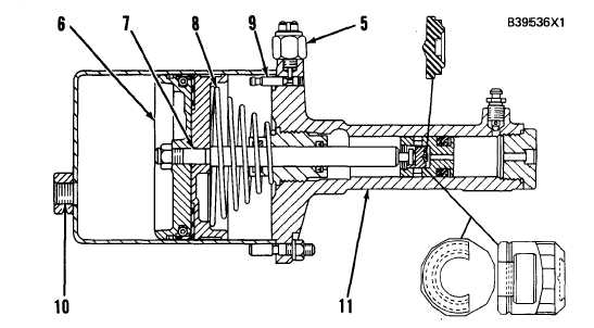
A I R C Y L I N D E R ( W i t h B r a k e s A c t i v a t e d )
5. Brake fluid pressure (overstroke) switch. 6. Piston. 7. Rod. 8. Spring. 9. Indicator
rod. 10. Air inlet. 11. Master cylinder.
When the brakes are released, spring (8) returns
the piston, rod and master cylinder piston to their
original positions.
If piston (6) comes in contact with indicator rod
(9), rod (9) will move and open switch (5). This
will cause the brake fluid pressure indicator to come
ON. If this does happen, there is a problem in the
hydraulic circuit for the wheel brakes. See the Test-
ing and Adjusting section on HOT OR DRAG-
GING BRAKES. After piston (6) comes in contact
with indicator rod (9), the rod must be manually
pushed back into the air cylinder to its original
position.
3-84