A I R S Y S T E M A N D B R A K E S
A I R C I R C U I T F O R T H E
W H E E L B R A K ES
higher pressure, and closes the inlet passage with the
lower pressure. Air then goes through outlet passage
(5) to the air cylinders.
AIR PRESSURE SWITCH FOR STOP LIGHTS
Air pressure switch (1) is activated when the air
pressure in the line to the air cylinders gets above
approximately 25 kPa (4 psi). When switch (1) is
activated, it causes the stop lights at the rear of the
machine to come ON.
Switch (1) is under the floor of the operator’s
station. It is fastened near the right brake control
valve.
TM 5-3805-258-24-1
S Y S T E M S O P E R A T I O N
L O C A T I O N O F A I R P R E S S U R E S W I T CH
1. Switch.
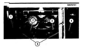
AIR CYLINDERS
The two air cylinders are part of the air/hydraulic
cylinders. Air cylinders (1) and (3) are under the
tool box at the rear of the cab.
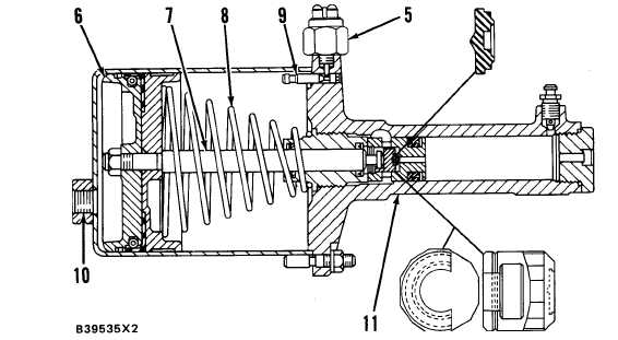
The air cylinder changes the energy of air under
pressure into force and movement needed for brake
application. The ratio of air pressure to brake fluid
pressure is 1 to 16. [If the pressure at air inlet (10)
is 70 kPa (10 psi), the pressure in the master cyl-
inder (11) is 1100 kPa (160 psi).]
When a brake pedal is pushed down, air under
pressure goes from the brake control valve to inlet
(10) of the air cylinder and pushes on piston (6).
R E A R O F C AB
Piston (6) pushes on rod (7), which pushes on a
1. Air cylinder for rear wheei brakes. 2. Master cylinder
f o r r e a r w h e e l b r a k e s . 3 . A i r c y l i n d e r f o r f r o n t w h e e l
piston in master cylinder (11). The rod is connected
b r a k e s . 4 . M a s t e r c y l i n d e r f o r f r o n t w h e e l b r a k e s . 5 .
to the piston in the master cylinder.
Brake fluid pressure (overstroke) switches.
A I R C Y L I N D E R ( W i t h B r a k e s R e l e a s e d )
5. Brake fluid pressure (overstroke) switch. 6. Piston. 7. Rod. 8. Spring. 9. Indicator
rod. 10. Air inlet. 11. Master cylinder.
3-83