TM 5-3805-258-24-1
H Y D R A U L I C
S Y S T E M
S Y S T E M S O P E R A T I O N
In operation with the lift hydraulic circuit is the
bucket lift kickout. It consists of lift detent lever
(13), a roller and linkage, lift kickout solenoid (14),
a magnet and lift kickout switch (21). The lift kick-
out moves lift control lever (8) from the raise detent
[on lever (13)] in RAISE position to the HOLD
position. This happens as the bucket lift arms
move from lower to raise when they get to correct
bucket lift height. There is also a FLOAT detent
on lift detent lever (13). The lever must be manually
moved out of the FLOAT detent position, there
is no kickout.
L E F T S I D E O F L O A D E R F R A ME
21. Lift kickout switch.
HYDRAULIC PUMP
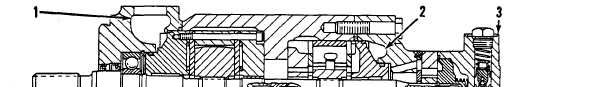
HYDRAULIC PUMP WITH THREE SECTIONS
1. Implement pressure outlet. 2. Steering pressure outlet. 3. Housing for pilot section
relief valve. 4. Implement section. 5. Inlet from tank. 6. Steering section. 7. Pilot section.
The hydraulic pump is a three section vane-type
pump. Steering section (6) and implement section
(4) are the cartridge type. The steering section pro-
vides the oil needed to operate the steering cylinders.
The implement section provides the oil needed to
operate the bucket and any attachments in the imple-
ment hydraulic system. Pilot section (7) is a straight
vane-type pump (it has no vane inserts). The pilot
section provides the oil needed to operate the hand
metering unit of the steering hydraulic system. It
also provides the oil needed to operate the pilot valves
of the implement hydraulic system.
All three pump sections get oil from the hydraulic
tank through inlet (5). Each section has its own
outlet. Pilot section (7) has a relief valve in housing
(4). The extra oil from the relief valve goes through
pilot drain outlet (2) and back to the tank.
Operation Of The Steering And Implement
Pump Sections
The components of both the steering and imple-
ment cartridges are similar: inlet and outlet support
plates, seal packs, flex plates, cam ring (1), rotor (2),
vanes (4) and inserts (9).
Since both pump sections (cartridges) are similar
only the description of one cartridge is given. Grooves
in the flex plates send pressure oil to slots (6) in rotor
(2). Oil from these slots goes into the area between
inserts (9) and vanes (4). This pushes the vanes out
against cam ring (1).
3-92