TM 5-3805-258-24-1
H Y D R A U L I C S Y S T E M
S Y S T E M S O P E R A T I O N
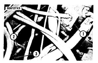
L O C A T I O N O F C H E C K V A L V E F O R
P I L O T P R E S S U R E O IL
1. Pilot pump section. 2. Check valve. 3. Line from selec-
tor and pressure control valve.
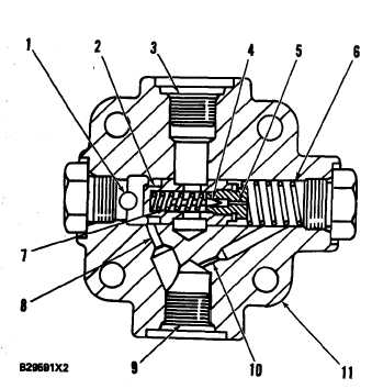
P I L O T S E C T I O N R E L I E F V A L VE
1. Inlet. 2. Valve. 3. Drain outlet. 4. Poppet. 5. Passage.
6 . S p r i n g . 7 . S p r i n g . 8 . O r i f i c e . 9 . O u t l e t . 1 0 . O r i f i c e .
11. Housing.
When pressures at inlet (1) and the chamber for
spring (6) are the same, spring (6) holds valve (2)
closed. During normal operation, the pressure from
inlet (1) is more than the pressure in the chamber
for spring (6) because of a decrease in pressure
across orifice (10). This causes valve (2) to move
against the force of spring (6) and the extra oil from
inlet (1) goes to drain outlet (3).
When the pressure through outlet (9) gets too high the
pressure causes poppet (4) to move against spring (7). The.
oil in the chamber for spring (6) now goes through
passage (5) and into drain outlet (3). There is now a
greater differrence between the pressures on the ends of
the valve (2). The valve moves farther against spring (6)
and permits a larger amount of oil to go through drain
outlet.
ONE-WAY CHECK VALVES
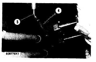
There are two one-way check valves in the imple-
ment hydraulic system. These valves permit the
flow of oil in one direction only. Check valve (2)
is in line (3) between the selector and pressure con-
trol valve and pilot pump section (1). Check valve
(4) is in line (5) between the head end of the lift
cylinders and the selector and pressure control
valve.
L O C A T I O N O F C H E C K V A L V E F OR
H E A D E N D L I F T C Y L I N D E R O I L
(View from under machine)
4. Check valve. 5. Line from selector and pressure control
valve.
During normal machine operation, check valve
(2) opens and lets pilot pressure oil go to the selector
and pressure control valve for operation of the
pilot valves. Check valve (4) will not let pilot pres-
sure oil go into the head end of the lift cylinders.
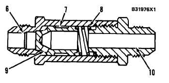
C O M P O N E N T S O F A C H E C K V A L VE
6. Inlet passage. 7. Valve. S. Spring. 9. Holes. 10. Out-
let passage.
3-94


