H Y D R A U L I C
S Y S T E M
TM 5-3805-258-24-1
S Y S T E M S
O P E R A T I O N
When the engine is off and the lift arms are raised,
check valve (4) will permit pressure oil from the head
end of the lift cylinders to go to the selector and
pressure control valve for operation of pilot valves.
Check valve (2) will not let the oil from the head end
of the lift cylinders go into the pilot pump section.
Pressure oil at inlet passage (6) pushes valve (7)
against spring (8). The oil is then free to go through
holes (9) in valve (7) and out outlet passage (10).
Pressure oil at outlet passage (10) pushes against
valve (7) and holds it closed. No oil can flow through
the check valve.
SELECTOR AND PRESSURE CONTROL VALVE
The selector and pressure control valve is in the
pilot oil system. It sends oil to the lift and tilt pilot
valve for its operation. The selector and pressure
control valve makes pressure oil available to the pilot
valve to lower a raised bucket (lift arms) when the
engine is off.
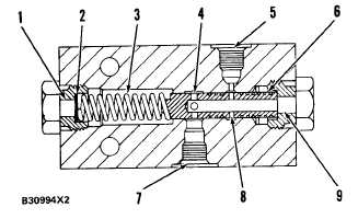
S E L E C T O R A N D P R E S S U R E C O N T R O L V A L V E
1. Drain passage. 2. Spacers. 3. Spring. 4. Holes (four). 5.
I n l e t p a s s a g e f r o m h e a d e n d o f l i f t c y l i n d e r s . 6 . V a l ve
spool. 7. Inlet passage from pilot pump section. 8. Holes
(two). 9. Outlet passage to lift and tilt pilot valve.
During normal operation, pressure oil from the pilot pump
section goes through inlet passage (7). The pressure of this
oil is controlled by the pilot relief valve. This oil goes
through holes (4) in valve spool (6), through the center of
the valve spool and out outlet passage (9) to the lift and
tilt pilot valve. This oil can not go through holes (8) and
out inlet passage (5). There is a check valve in this line to
stop the flow of oil to the head end of the lift cylinders.
When the engine is off, there is no pressure oil at inlet
passage (7). When the engine is off and the lift arms are
raised, the pressure from the head end of the lift cylinders
is in inlet passage (5). This oil is stopped (held) in the
lines as long as the lower stem in the lift and tilt pilot
valve is in the HOLD position. When the lower stem is
moved to LOWER position, the pressure oil from the head
end of the lift cylinders can now go through holes (8) in
valve spool (6), through outlet passage (9), the pilot valve,
and on to the lift valve spool in the lift and tilt control
valve. The lift valve spool moves to LOWER position and
the lift the lift arms will lower. A check valve in the line
from inlet passage (7) will not let oil go to the pilot pump
section.
NOTE: When the engine is off and the lift arms are
raised, the bucket can also be dumped.
When the engine is off, valve spool (6) also con-
trols the pressure of the oil from inlet passage (5) to
the pilot valve [approximately 1030 kPa (150 psi)].
When the pressure through outlet passage (9) gets
too high, the pressure will cause valve spool (6) to
move against the force of spring (3). This decreases
the flow of oil through holes (8) in the valve spool and
decreases the pressure in outlet passage (9).
LIFT AND TILT PILOT VALVE
The lift and tilt pilot valve is controlled manually
by the operator. It sends oil from the pilot system to
the lift and tilt control valve which controls the oper-
ation of the lift and tilt cylinders. There are four
valve stems (of the pressure metering type) in the lift
and tilt pilot valve. Two valve stems are needed for
each operation of lift and tilt.
When a lift or tilt control lever is moved, one
plunger is pushed down in the pilot valve. The
plunger causes a valve stem to move down and send
pilot oil to one end of a valve spool in the lift and tilt
control valve. The valve spool then moves and pushes
oil, from the opposite end of the valve spool, out of the
lift and tilt control valve. The oil goes back to the
pilot valve to another valve stem. The oil then goes to
drain through tank passage (11).
Three of the valve stems in the pilot valve are the
same: dump stem, tilt back stem and lift stem (13).
Lower stem (12) is longer than the other three stems.
All four stems are held in place the same way.
HOLD Position Of Lift Operation
When the lift control lever is in HOLD position,
plungers (3) and (4) are in the same position (as
shown). The plungers do not push up against actua-
tor (1) in the hold position. Pressure oil from the pilot
pump section goes through pump passage (20) and is
stopped by the position of stems (12) and (13). Holes
(14) and (15) are open to tank passage (11).
3-95