9 5 0 B S T E E R I N G S Y S T E M
S T E E R I N G C O N T R O L V A L VE
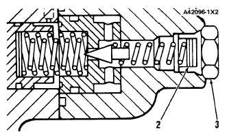
2. Shims. 3. Plug.
If the pressure is not correct:
a. Remove plug (3) from steering control valve.
b. Add shims (2) to increase the pressure setting
and remove shims if a decrease is necessary.
PRESSURE CHANGE FOR ONE SHIM (2)
Part No.
Thickness
Pressure Change
3 H 2 5 4 9
0.25 mm (.010 in.)
3 4 0 k P a ( 5 0 p s i )
STEERING SLIP CHECK
To check the steering wheel slip:
1. Put the machine on a dry hard surface. Raise the
bucket and release the brakes.
2. With the engine at low idle, turn the steering
wheel slowly through one revolution so that there
is a minimum of articulation. Do this in both
directions to get the feel of the steering action.
3. Do this test three more times in each direction.
Make a note of the time required for each of the
revolutions of the steering wheel.
4. Add the three times for each direction. If these
totals are 60 seconds or more, the slip is
acceptable.
5. If the totals are less than 60 seconds, remove the
spool from the steering control valve. Turn the
spool around in its bore (turn end for end). To do
this the spring, retainer and shims must be in-
stalled on the opposite end of the spool. On some
machines this will correct the problem of manu-
facturing tolerances and the slip will then be
TM 5-3805-258-24-1
T E S T I N G A N D A D J U S T I N G
NEUTRALIZER VALVE
L E F T
N E U T R A L I Z E R
V A L VE
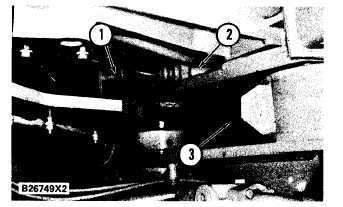
1. Striker. 2. Neutralizer valve. 3. Frame stop (one on each side
o f m a c h i n e ) .
To check the adjustment of striker (1):
1.
2.
3.
4.
5.
Put a 12.7 mm (.50 in.) ball of putty (or similar
material) on both frame stops (3).
Raise an empty bucket about 30 cm (12 in.) and
release the brakes.
With the engine at high idle, steer rapidly into
both stops.
Thickness of the putty must be 9.7 ± 3.7 mm
(.38 ± .12 in.) after the turns. This is the clear-
ance between the frame stops when a full turn
is made.
If the clearance is not correct, adjust the strikers
until the dimension is correct.
acceptable.
4-55


