TM 5-3805-258-24-1
9 5 0 B S T E E R I N G S Y S T E M
T E S T I N G
A N D
A D J U S T I N G
3. Shims (2) are available in two thicknesses.
5J4776 Shims are 0.13 mm (.005 in.) thick.
4J8224 Shims are 0.25 mm (.010 in.) thick. Two
4J8224 Shims will change the steering time at
high idle by approximately .1 second.
EXAMPLE: A check of the steering times shows
that the right turn time is .4 second more than the left
turn time. Shims (2) must be added to decrease the
difference between the times. The addition of four
4J8224 Shims will decrease the right turn time by
approximately .2 second and increase the left turn
time approximately .2 second. This will make the
right and left turn times approximately the same.
4. Replace the end cover on the control valve.
the
lets
2.
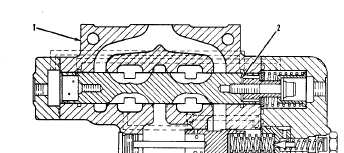
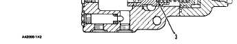
S T E E R I N G C O N T R O L V A L VE
1. Control valve. 2. Flow balance shims. 3. Cylinder flow
s h i m s .
If both steering times (right and left) are slow,
cylinder flow shims (3) must be added.
4J6806 Shim thickness . . . . . . . . . . .
1.22 mm (.048 in.)
One shim will change the steering times at high
idle by approximately .1 second.
PRESSURE TEST OF STEERING SYSTEM
Loosen the filler cap on the tank to permit the
pressure in the tank to go down before installa-
tion or removal of any test equipment.
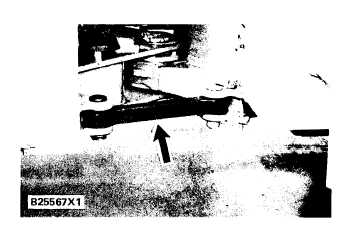
1. Install the anti-pivot link so the machine can
not turn.
A N T I - P I V O T L I N K I N S T A L L ED
NOTE: If the anti-pivot link can not be installed, the
pressure setting can be checked by an adjustment of
striker (stud assembly) that is not correct. This
the front and rear frame stops come in contact.
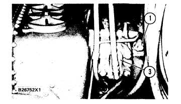
Remove plug (1) and install a 2P1314 Con-
nector where plug (1) was removed. Install the
7S8714 Pressure Gauge (0 to 4000 psi or 0 to
28000 kPa) and the
connector.
6V3081 Hose on the
S T E E R I N G C O N T R O L V A L VE
1. Plug. 3. Plug.
Alternate Step 2. Remove plug (1) and perma-
3.
4.
nently install a 6V3965 Valved Nipple where
plug (1) was removed. Connect 6V3081 Hose
to the nipple with a 6V4143 Coupler. Install
the 7S8714 Pressure Gauge.
Start the engine and operate it at high idle.
Turn the steering wheel until the relief valve
opens. Note the indication on the gauge. The
correct relief pressure is 17200 ± 340 kPa
(2500 ± 50 psi).
4-54