A I R S Y S T E M A N D B R A K E S
TM 5-3805-258-24-1
T E S T I N G
A N D
A D J U S T I N G
AIR SYSTEM AND BRAKES
WARNING
Before making any tests or adjustments on the
brake system, stop the machine on level
ground. Move the control knob for the parking
brake to the ON position. Put blocks in front of
and behind the wheels. Permit only one man on
the machine. Keep all other personnel away
from the machine. Never disconnect any air or
brake fluid lines in the brake system until all
pressure is removed. Failure to remove this
pressure will have a sudden release of air or
brake fluid under high pressure. This can cause
injury to personnel. To remove the pressure
from the brake system: Engage the parking
brake. Stop the engine. Push on either brake
pedal many times until there is no more brake
air pressure. When the pressure has been re-
moved from the air circuit, there will be no
pressure in the brake hydraulic circuit.
NOTE: Before any operation checks are made, open
the drain valve to release any water in the air reser-
voir. Water lowers the capacity in the reservoir and
can cause the air compressor to-run constantly. Close
the drain valve.
VISUAL CHECKS
Before any operation checks are made to the air
system and brakes, visually inspect the complete
system as follows:
1.
2.
3.
4.
Check for cracks or wear in hoses and lines.
Check for restriction of flow; like sharp bends,
clamps that are not installed correctly, and dam-
age to hoses and lines.
Check for loose connections.
Check for damage to components.
AIR RELIEF VALVE
The relief valve opens at 1030 kPa ( 150 psi) and has
no adjustment.
CHECKS FOR LEAKAGE IN AIR CIRCUIT
T o o l s N e e d e d : 0 t o 1 3 8 0 k P a ( 0 t o 2 0 0 p s i ) G a u g e .
WARNING
Make reference to WARNING on first page of
AIR SYSTEM AND BRAKES TESTING AND AD-
JUSTING section.
NOTE: It is possible to hear the sound of air leakage.
Air leakage can be seen when water with soap (soapy
water) is put on the connections, valves and hoses.
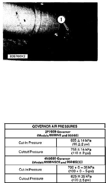
L O C A T I O N T O I N S T A L L G A U GE
1. Drain valve for the air reservoir.
1. Install a 0 to 1380 kPa (0 to 200 psi) gauge in
drain valve (1) for the air reservoir.
2. Start the engine and let the air pressure go up to
the cutout pressure. Stop the engine.
NOTE: See chart for correct governor cutout pressure
If cutout pressure is not correct, see the subject, AIR
COMPRESSOR GOVERNOR.
GOVERNOR AIR PRESSURES
I
2P7809 Govarnor
(Models 950BNS and 950BS)
Cut-In Pressure
655 k 14 kPa
(95 t 2 psi)
Cutout Pressure
758 k 14 kPa
(110&2 psi)
4N9680 Governor
(Medals 950BNSCE and 950 BSCE)
Cut-In Pressure
700 + O – 35 kPa
(100 +0-5 psi)
Cutout Pressure
825 ? 35 kPa
(120 * 5 psi)
4-59