TM 5-3805-258-24-2
ENGINE
FUEL
DISASSEMBLY AND ASSEMBLY
INJECTION PUMP HOUSING AND GOVERNOR
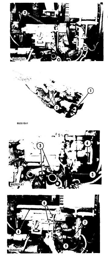
14. Fasten a strap and hoist to fuel injection pump
housing and governor (21) as shown.
15. Pull drain line (22) from the clip on the engine
block.
16. Remove fuel injection pump housing and gov-
ernor (21). The weight of the fuel injection
pump housing and governor is 26 kg (58 lb.).
INSTALL FUEL INJECTION PUMP HOUSING
AND GOVERNOR
1286-12
Tools Needed
A
B
6V4186
Pin
1
FT 1644
Adapter
1
1. Put O-ring seals (1) and (2) in position on the
fuel injection pump housing and governor. Put
clean oil on the O-ring seals.
2. Put the fuel injection pump housing and gover-
nor in position on the oil manifold and the
timing gear plate with bolts (3) and nuts (4).
3. Put drain line (5) into position on the clip on the
engine block.
CAUTION
After the fuel injection pump housing and gov-
ernor are installed on the timing gear plate, be
sure the rack is free to move. The O-ring seal
(1) on the drive end of the fuel injection pump
can hold the rack and prevent free movement
of the rack. If the rack does not move freely,
remove the fuel injection pump housing and
governor and check the O-ring seal on the drive
end of the fuel injection pump housing.
4.
5.
Install heat shield (8) between the manifold
and fuel injection pump housing and governor.
Tighten the bolt to a torque of 23 ± 4 N·m (17
± 3 lb.ft.).
Connect tube assemblies (6) and hose assembly
(7) as shown.
6. Install bolt (9) that holds the clip.
5-94