ENGINE
TM 5-3805-258-24-2
DISASSEMBLY AND ASSEMBLY
ROCKER SHAFT AND PUSH RODS
REMOVE ROCKER SHAFT AND
PUSH RODS
1102 & 1208-11
start by:
a) remove valve cover
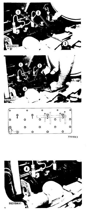
1. Remove four bolts (l) and the washers from the
rocker shaft.
2. Remove rocker shaft (2) from the cylinder
head.
3. Remove push rods (3) from the engine.
INSTALL ROCKER SHAFT AND
PUSH RODS
1102 & 1208-12
1.
2.
3.
4.
Loosen adjusting screws (1) on the rocker arms
for valve clearance. This will prevent a bent
valve or push rod at installation.
Install push rods (3) as shown.
Put rocker shaft (2) in position on the cylinder
head.
Put 5P3931 Anti-Seize Compound on the
threads of the bolts (except the rear bolt fly-
wheel end) that holds the rocker shaft in posi-
tion. Install the four bolts and washers.
NOTE: Make sure the rocker arms are on all of the
push rods.
CAUTION
The dowels on each end of the rocker shaft
assembly must make an alignment with the
holes in the cylinder head assembly. If the
dowels and holes are not in alignment when the
rocker shaft assembly is tightened, damage to
the rocker shaft assembly will be the result.
5.
6.
7.
Tighten the bolts for the rocker shaft as follows:
a)
b)
c)
Tighten bolts in number sequence to a tor-
que of 155 N·m (115 lb.ft.).
Tighten bolts again in number sequence to
a torque of 250 ± 17 N·m (185 ± 13
lb. ft.).
Tighten bolts again and for the last time in
number sequence (hand tighten only) to a
torque of 250 ± 17 N·m (185 ± 13 lb. ft.).
The assembled length of springs (4) at both
ends of the rocker shaft must be 1.50 ± 0.25
mm (.059 ± .010 in.). Remove or install the
washers behind springs to change the assem-
bled length of the springs.
Make adjustments until the intake valve clear-
ance is 0.38 mm (.015 in.) and the exhaust
valve clearance is 0.64 mm (.025 in.). See EN-
GINE VALVE LASH as shown in MAINTE-
NANCE GUIDE. Tighten the locknuts for the
adjusting screws to a torque of 29 ± 7 N·m (21
± 5 lb. ft.).
end by:
a) install valve cover
5-121