TM 5-3805-258-24-2
POWER TRAIN
FRONT AND REAR
17.
18.
19.
20.
21.
22.
Heat bearing cone (24) to a maximum temper-
ature of 135°C (275°F). Install bearing (24)
Fasten a hoist to housing (21) with tooling (B).
Put housing (21) in position on the pinion and
bearing.
Heat bearing cone (25) to a maximum temper-
ature of 135° C (275° F) and install it on-the
pinion shaft as shown.
NOTE: Models 950BNSCE and 950BSCE use
a nut and keyed washer rather than two nuts
and a lock.
Install nut (28) on the pinion shaft and put oil
on bearings. While the pinion is slowly turned,
tighten nut (28) with tool (E) until the torque
needed to turn the pinion is 0.9 ± 0.2 N-m (8 ±
2 lb.in. for new bearings).
If original bearings are used, tighten nut
until torque to turn pinion is 0.5 ± 0.2 N-m (4
± 2 lb.in.). Put clean oil on lock (27) and install
it on the pinion shaft. Install nut (26) with tool
(E) on the pinion shaft. Bend the tab of the
lock in the groove of nut (26). On models
950BNSCE and 950BSCE peen nut collar into
key into key slot of shaft. Check the torque
needed to turn the pinion. The torque still
must be 2.0 ± 0.2 N-m (18 ± 2 lb.in.) for new
bearings and 0.5 ± 0.2 N-m (4 ± 2 lb.in.) for
used bearings. If the torque is not correct, an
adjustment must be made to nut (28).
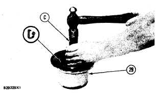
Use tool group (C) and install the seal in re-
tainer (29). Make sure the lip of the seal is
toward the inside of retainer (29) as shown. Put
clean oil on the lip of the seal after installation.
DISASSEMBLY AND ASSEMBLY
DIFFERENTIALS
5-206


