TM 5-3805-258-24-2
POWER TRAIN
DISASSEMBLY AND ASSEMBLY
FRONT AND REAR DIFFERENTIALS
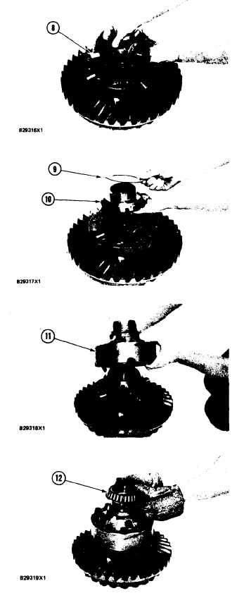
5. Install the gears and spider (8) in the case.
6. Install washer (9) on gear (10) and put the gear
in position in the case.
7. Install case (11) on case (2). Make sure the
marks on the cases are in alignment, and install
the bolts that hold the cases together. Tighten
the bolts to a torque of 135 ± 15 N-m (100
± 11 lb.ft.).
8. Heat the bearing cone to a maximum tempera-
ture of 135°C (275 °F).Install bearing cone(12)
on the case.
NOTE: There are differences between models
of the Loader in this procedure. Those places
where there are differences are annotated in
the text.
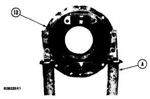
9. Put carrier assembly ( 13) in position on tooling
(A) as shown.
5-204


