TM 5-3805-258-24-2
OPERATOR’S STATION
INSTRUMENT
REMOVE INSTRUMENT PANEL
1.
2.
3.
4.
5.
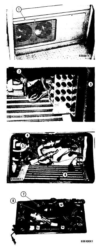
Use the ¼” square drive wrench that comes
with the machine to turn the locks counter-
clockwise and open panel (1) on the right side
of the machine.
Remove the bolts and nuts that hold fuse panel
(3) in position. Disconnect wiring harnesses (2)
from the fuses and remove fuse panel (3) from
the machine.
Disconnect wiring harnesses (4), (5) and (6)
from the instrument panel wiring.
Loosen the two screws and strips that hold the
bottom of the instrument panel to the machine.
Remove the instrument panel from the inside of
the cab.
Remove the four nuts (7) and washers to re-
move the systems monitor group (8) from the
instrument panel.
NOTE: The individual parts of monitor group (8)
are not serviced separately.
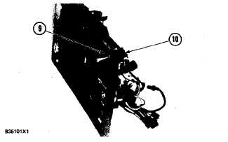
6. Remove panel test switch as follows:
a) Disconnect the two wires from the back of
switch (10). Put identification on the wires
for correct installation.
7. Remove nut (9). Remove switch ( 10) from the
back of the panel.
DISASSEMBLY AND ASSEMBLY
PANEL
5-496