TM 5-3805-258-24-2
OPERATOR’S STATION
DISASSEMBLY AND ASSEMBLY
GOVERNOR PEDAL GROUP
Models 950BNS and 950BS
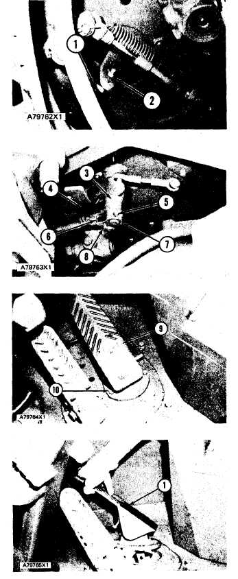
REMOVE GOVERNOR PEDAL
GROUP
1265-11
1. Remove nut (2) and disconnect rod assembly (1)
from the lever.
2. Remove cotter pin (8) and washer. Disconnect
yoke (6) from the lever.
3. Remove spring (4).
4. Remove cotter pin and pin (5). Remove collar
(7). Remove lever assembly (3).
5. Remove three bolts (10). Remove governor ped-
al (9) and base assembly as a unit.
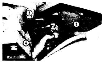
INSTALL GOVERNOR PEDAL
GROUP
1265-12
1.
2.
3.
4.
5.
6.
Put governor pedal (1) and base assembly in
position. Install the bolts that hold it.
Put lever assembly (3) in position. Install the
collar, pin and cotter pin that hold it on the shaft.
Install the spring on the lever assembly.
Connect yoke (4) to the lever assembly.
Connect rod assembly (2) to the lever assembly.
Make an adjustment to the pedal assembly so it is
at a 66° ± 3° angle with the floor when the engine
governor shaft is in the “OFF” position.
5-501