TM 5-3805-258-24-2
OPERATOR’S STATION
DISASSEMBLY AND ASSEMBLY
BLACKOUT
REMOVE LIGHTING CONTROL RELAYS
1.
2.
Remove instrument panel. Refer to: Remove
Instrument Panel (preceding section).
There are seven control relays for the lighting
control circuit. The seven relays are located
under the instrument panel which was re-
moved in step (1). Four of the relays are
mounted on a bracket at the back of the
Instrument panel and wiring harness enclosure
and the other three relays are mounted on a
bracket towards the front.
NOTE: Tag all wiring before disconnecting the
wiring from the relay(s).
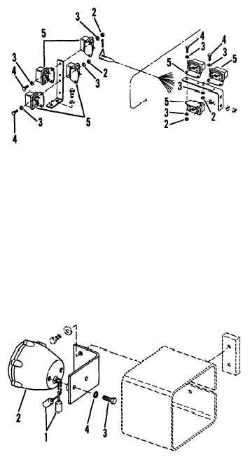
3. All of the relays are mounted in the same
manner. To remove a relay, pull wiring har-
ness connectors (1) off of the relay terminals.
4. Remove two nuts (2), washers (3), bolt (4)
and relay(s) (5).
INSTALL LIGHTING CONTROL RELAYS
1.
2.
3.
Secure relay(s) (5) with bolt (4), washers (3)
and nuts (2).
Push wiring harness connectors (1) on the
relay terminals. Use tags made during removal
for wire identification.
Install instrument panel. Refer to: Install
Instrument Panel (preceding section).
REMOVE BLACKOUT TAIL LAMP ASSEMBLY
1. Disconnect wiring (1) from the back of the
blackout tail lamp (2).
2. Remove capscrews (3), lockwashers (4), and
blackout tail lamp (2).
INSTALL BLACKOUT TAIL LAMP ASSEMBLY
1.
2.
Secure blackout tail lamp (2) with lock-
washers (4) and capscrews (3).
Connect wiring (1) to the back of the black-
out tail lamp.
LIGHTING
5-500b