TM 5-3805-262-20
INSPECTION
(4)
AND REPAIR (SHEET 2 OF 4)
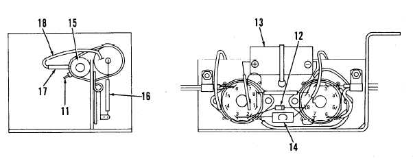
Inspect relay socket assembly diode (12) and resistors (14 and 15) for
c r a c k s , b r e a k s, and discoloration due to overheating. Inspect capacitor
(13) for deformation or broken wire leads at body. If any of the above
conditions are seen, replace defective component as follows:
( a ) C u t , r e m o v e , a n d d i s c a r d t i e s t r a p ( 1 1 ) .
(b) Unsolder leads of diode (12), capacitor (13), or resistor (14 or 15)
and disconnect from relay socket terminals. Remove resistor (15) by
cutting silicone rubber adhesive between resistor body and relay
socket assembly using sharp knife.
(c) Apply thin bead of silicone rubber adhesive on body of new resistor
(15) and position resistor on relay socket assembly.
( d ) P u s h e n d o f n e w t i e s t r a p t h r o u g h h o l e i n r e l a y s o c k e t a s s e m b l y a nd
i n s t a l l t i e s t r a p a r o u n d r e s i s t o r ( 1 5 ) a n d c a p a c i t o r ( 1 3 ).
(e) Slide new heat shrink tubing (16) over positive lead of new capacitor
( 1 3 ).
( f ) C o n n e c t o n e e n d o f w i r e s ( 1 8 ) t o r e s i s t o r ( 1 5 ) l e a d s a n d s o l d e r . S l i de
new heat shrink tubing (17) onto wires and position over connections.
In following step position bare wire leads of resistor (14) at least 1/4
inch from all other metal to prevent short circuit.
(g) Connect and solder leads of diode (12), capacitor (13), or resistor
(14 or 15) to relay socket terminals.
(h) Secure heat shrink tubing (16 and 17) using air blast from electric
heat gun.
5-79