TM 5-3805-262-34
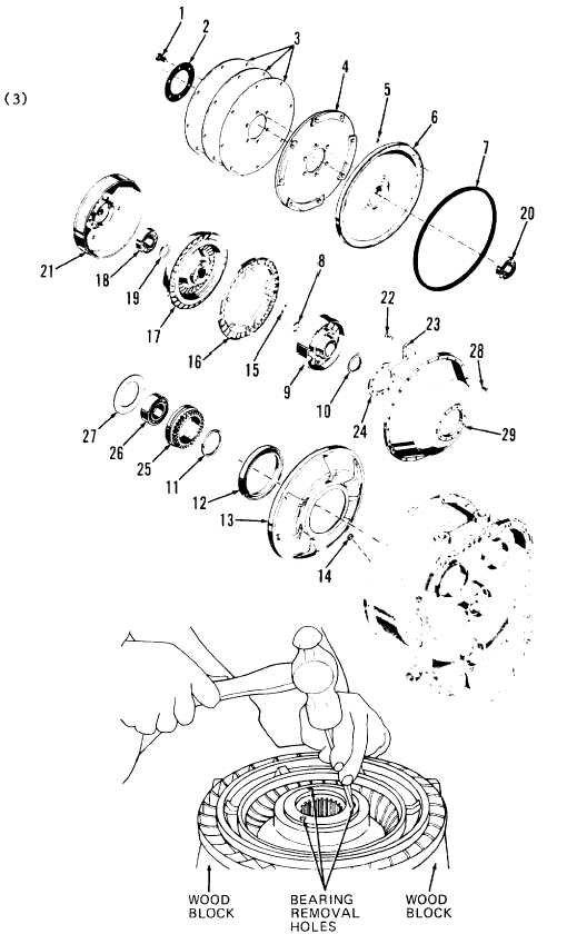
DISASSEMBLY (SHEET 2
LEGEND
1.
2.
3.
4.
5.
6.
7.
8.
9.
10.
11.
12.
13.
14.
15.
16.
17.
18.
19.
20.
21.
22•
23.
24.
25.
26.
27.
28.
29.
Capscrews (6)
Retaining plate
Flex plate disks
Flex plate disk
Lock nuts (24)
Converter cover
Seal
Retaining ring
Stator
Spacer
Seal
Oil seal
Diaphragm
Plug
Turbine pins (6)
Turbine
Turbine assembly
Bearing
Retaining ring
Bearing
Turbine housing
Capscrews (12)
Lock plates (6)
Retaining plate
Drive gear
Bearing
Seal
Capscrews (24)
Converter pump
(7)
( 8)
OF 3)
Put turbine assembly
(17) on wood blocks.
Using hammer and
punch, remove bearing
(18) using bearing re-
moval holes in turbine
assembly.
If not already accom-
plished, bend tabs of
lock plates (23) away
from heads of cap-
screws (22).
4-99

