TM 5-3805-262-34
3-2. FUEL SYSTEM MAINTENANCE (CONT)
d. Fuel Injection Pump (Cont).
REMOVAL (
(3)
(4)
(5)
In
and
(6)
(7)
(8)
(9)
(lo)
(11)
SHEET 2 OF 2)
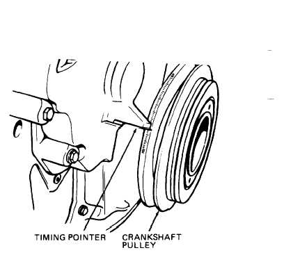
Crank engine counterclockwise
to 35 degree mark.
Crank engine clockwise until
timing pointer is alined with
27 degree mark on crankshaft
pulley (injection pump timing).
Cut wire (1) and pull from
holes in capscrews (4) and stud
(21), then remove and discard
wire (1) with seal (2).
NOTE
following two steps, note locations of gear cover capscrews (3, 4,
6) to aid proper installation.
Remove four capscrews (3 and 4) and lock washers (5).
Remove capscrew (6), lock washer
(7), gear cover (8), and gasket
(9). Discard gasket (9).
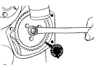
Measure drive gear (12) to
idler gear backlash using dial
indicator. Backlash must be
less than 0.012 inch. Then
remove three capscrews (10),
lock washers (11), and drive
gear (12).
Remove plug (13) and gasket (14).
Support fuel injection pump (19) and remove four nuts
washers (17), and washers (18).
(15 and 16), lock
Remove fuel injection pump (19) with governor as an assembly.
NOTE
Don-t remove studs (20 and 21) unless inspection indicates need for
replacement. Note location of stud (21) having drilled hole to aid
installation.
3-138