TM 5-3805-262-34
TEST NO. 2 - STEERING CIRCUIT AND RELIEF VALVE (SHEET 3 OF 5)
g.
Connect flowmeter (12) hoses (10 and 11) and adapters and assemble adapters
and nine inch return pipe (13) (p/o flowmeter fitting kit) as shown. Install
assembled parts (13) in fill cap opening of hydraulic reservoir.
h.
Install flowmeter in loader cab.
i.
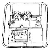
Set flowmeter controls as follows;
RANGE switch in HI position
ON/OFF switch in ON position
PRESSURE VALVE control completely open
FLOW switch in FLOW position
j.
Start and operate engine at idle speed.
k.
Press and hold flowmeter TEMPERATURE switch
and watch flowmeter TEMPERATURE gage. Gage
should indicate 130 degrees. If indication is
not correct go to step 1 below; if gage
indicates 130 degrees go to step m below.
Before performing following steps, warn personnel to stay away from
sides of loader between front and rear chassis. Failure to do so will
cause death or serious injury to those personnel due to chassis pivoting
and crushing them. If personnel are injured, obtain medical assistance
immediately.
l.
Depress accelerator pedal and increase engine speed to 1500 rpm. Turn
steering wheel completely to right until it cannot be turned anymore.
Continue to hold steering wheel for a full right turn. Close flowmeter
PRESSURE VALVE control until flowmeter PRESSURE gage indicates 1000 psi.
Watch flowmeter TEMPERATURE gage while depressing flowmeter TEMPERATURE
switch. Continue to operate engine at 1500 rpm until flowmeter gage indi-
cates 130 degrees then release accelerator pedal.
m.
Increase engine speed to full throttle.
n.
Turn steering wheel to right and slowly close flowmeter PRESSURE VALVE
control. As PRESSURE VALVE control is closed, flowmeter FLOW gage indication
will slowly decrease. When loader relief valve begins to open, flowmeter
FLOW gage reading will decrease rapidly. Stop closing flowmeter PRESSURE
VALVE control and record flowmeter PRESSURE gage reading. This reading is
the pressure at which relief valve begins to open.
3-507


