TM 5-3805-262-34
3-23. CONTROL LEVERS AND LINKAGES MAINTENANCE (CONT)
REASSEMBLY (SHEET 1 OF 2)
a.
b.
c.
d.
e.
f.
g.
h.
i.
j.
k.
l.
3-714
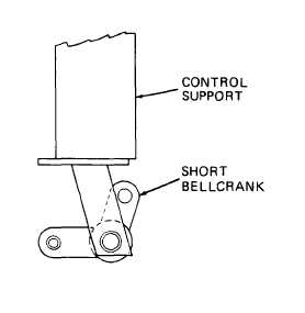
Place control support (46) on a flat surface
with control cover mounting holes upward.
Insert smooth end of shaft (44) through one
bottom hole of control support (46). Install
three bellcranks (45) on shaft. Be sure to
position bellcranks as shown.
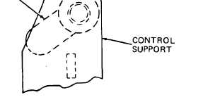
Install smooth end of shaft (44) through
opposite hole in control support (46). Use
hammer to press knurled end of shaft into
control support.
Insert smooth end of shaft (42) through one
top hole of control support (46). Install
three bellcranks (43) on shaft. Be sure to
position bellcranks as shown.
Install smooth end of shaft (42) through
opposite hole in control support (46). Use
hammer to press knurled end of shaft into
control support.
If removed, install six lubrication fittings
(40 and 41) in bellcranks (43 and 45).
Install bottom lip of three seals (37) in
seal retainer (38) holes.
Position seal (39) and seal retainer (38) with seals (37) installed on con-
trol support (46). Secure using four capscrews (36), washers (35), lock
washers (34), and nuts (33).
Carefully install three control link rods (32), threaded end first, up
through bottom of control support (46) and through seals (37). Hold seals
(37) when installing rods to prevent stretching and possibly tearing seals.
Install three nuts (29) and clevis (28) on control link rods (32). Adjust
clevis to obtain 14.5 inches between center of clevis pin mounting holes
at top and bottom clevis installed on rods. Tighten nuts on rods against
clevis to secure adjustment.
Connect clevis at bottom of control link rods (32) to bellcranks (45) using
three clevis pins (31) and cotter pins (30).
Connect clevis (28) at top of control link rods (32) to bellcranks (43) us-
ing three clevis pins (27) and cotter pins (26).