TM 5-3805-262-34
REASSEMBLY (SHEET 2 OF 2)
m.
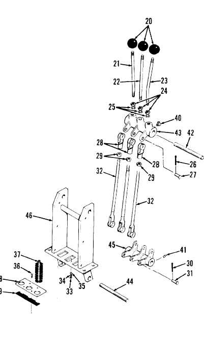
Put a nut (24) and lock washer (25) on each control lever (21 thru 23). In-
stall control levers with nuts and lock washers in bellcranks (43). Tighten
nuts securely against bellcranks to secure control levers.
n.
Install three knobs (20) on control levers (21 thru 23).
LEGEND
20. Knobs (3)
21. Clam control lever
22. Bucket control lever
23. Lift arm control lever
24. Nuts (3)
25. Lock washers (3)
26. Cotter pins (3)
27. Clevis pins (3)
28. Clevis (3)
29. Nuts (3)
30. Cotter pins (3)
31. Clevis pins (3)
32. Control link rods (3)
33. Nuts (4)
34. Lock washers (4)
35. Washers (4)
36. Capscrews (4)
37. Seals (3)
38. Seal retainer
39. Seal
40. Lubrication fittings (3)
41. Lubrication fittings (3)
42. Shaft
43. Bellcranks (3)
44. Shaft
45. Bellcranks (3)
46. Control support
3-715

