TM 5-3805-262-34
3-23. CONTROL LEVERS AND LINKAGES MAINTENANCE (CONT)
ADJUSTMENT (SHEET 1 OF 3)
a.
b.
c.
d.
e.
f.
g.
h.
i.
j.
k.
3-718
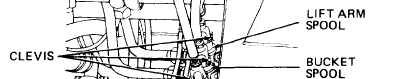
Position machinist’s rule on control
valve body next to lift arm spool.
Using end of clevis as a reference
point, tell assistant to place LIFT
ARM control lever in RAISE position
while you measure travel of clevis.
Clevis should travel approximately
0.44 inch.
Tell assistant to place
LIFT ARM control lever in
NEUT. position then move
it to LOWER position while
you measure travel of
clevis from NEUT. to LOWER
position. Clevis should
travel approximately 0.44
inch.
Tell assistant to place LIFT ARM
control lever in NEUT. position then
move it to FLOAT position while you
measure travel of clevis from NEUT.
to FLOAT position. Clevis should
travel approximately 0.88 inch.
If dimensions obtained above are okay, go to step m below otherwise go to
step f below to adjust LIFT ARM control linkage.
Remove cotter pin (3) and clevis pin (4) securing lift arm control link rod
(5) clevis to bellcrank.
To decrease movement, loosen nut (8) and turn clevis (9) counterclockwise
on lift arm control link rod (5). To increase movement, loosen nut (8) and
turn clevis (9) clockwise.
Tighten nut (8) against clevis (9).
If necessary, remove cotter pin (1) and clevis pin (2) securing lift arm
control link rod (5) clevis to control valve assembly lift arm spool.
To decrease movement, loosen nut (8) and turn clevis (9) counterclockwise
on lift arm control link rod (5). To increase movement, loosen nut (8) and
turn clevis (9) clockwise.
Tighten nut (8) against clevis (9).