TM 5-3805-262-34
ADJUSTMENT (SHEET 2 OF 3)
l.
m.
n.
o.
P.
q.
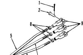
Position lift am control link rod (5) clevis (9) between bellcrank and
control valve assembly lift am spool. Install clevis pins (2 and 4) and
cotter pins (1 and 3). Repeat steps a through e above to check adjustment.
Position machinist’s rule on control valve body next to bucket tilt spool.
Using end of clevis as a reference point, tell assistant to place BUCKET
control lever in DUMP position while you measure travel of clevis. Clevis
should travel approximately 0.44 inch.
Tell assistant to place BUCKET control lever in NEUT. position then move it
to CROWD position while you measure travel of clevis from NEUT. to CROWD
position. Clevis should travel approximately 0.44 inch.
If dimensions obtained above are okay, go to step x below otherwise go to
step q below to adjust BUCKET control linkage.
Remove cotter pin (3) and clevis pin (4) securing bucket tilt control link
rod (6) clevis to bellcrank.
LEGEND
1. Cotter pins (3)
2. Clevis pins (3)
3. Cotter pins (3)
4. Clevis pins (3)
5. Lift am control link rod
6. Bucket tilt control link rod
7. Clam control link rod
8. Nuts (6)
9. Clevis (6)
BELLCRANKS
3-719